Fluid disinfection apparatus and method

a technology of disinfection apparatus and fluid, which is applied in the field of apparatus for disinfection fluid and to a method of disinfection fluid, can solve the problems of destroying the dna of any microorganism, killing or inactivating microorganisms, and being particularly difficult to achiev

Inactive Publication Date: 2009-01-01
GB ENVIRONMENTAL
View PDF4 Cites 4 Cited by
  • Summary
  • Abstract
  • Description
  • Claims
  • Application Information

AI Technical Summary

Benefits of technology

[0010]The intensity of the radiation decreases as it passes through the fluid. However, the relative rotation of the members creates a turbulent flow of fluid within the apparatus to ensure that the fluid circulates and swirls close to the opposed surfaces of the members, thereby ensuring that all parts of the fluid are exposed to an intense dose of radiation. In this manner it is found that the disinfection rate increases with an increase in the relative rotation of the members, since this increases the agitation of the fluid.
[0019]The turbulent flow further creates a scrubbing action upon the surfaces of the members which prevents the build up of material on said surfaces which may reduce the transmission of the radiation into the fluid, and thus the disinfecting ability.
[0026]Preferably, the spacing between the members is adjustable axially of the direction of rotation of the first member. Preferably, the fluid passes into the apparatus under a controlled pressure. By controlling the pressure at the inlet and maintaining a consistent separation of the members, a controlled flow of fluid can be maintained through the apparatus, independently of the viscosity of the fluid.

Problems solved by technology

The germicidal effect of UV light occurs when the UV light is transmitted through the liquid and results in the disruption of the DNA of any micro-organisms within the liquid, thereby killing or inactivating the micro-organisms.
This can be particularly difficult if the water is viscous or contains a lot of waste material, since the UV light can become totally absorbed after penetrating only a short distance.
In these circumstances, a large amount of energy is required to produce the high intensity UV light that is required to penetrate the water.
Consequently, known UV light disinfection techniques, such as that disclosed in EP0202891 cannot satisfactorily disinfect these types of liquids.
This process requires a large amount of energy and results in a degradation in the taste of the liquid.
The accepted view therefore is that UV disinfection is not practical for liquids having such a low transmission coefficient for UV light, since it would require the use of extremely high intense UV light combined with a very low processing rate.

Method used


Image

  • Fluid disinfection apparatus and method
  • Fluid disinfection apparatus and method
  • Fluid disinfection apparatus and method

Examples


Embodiment Construction

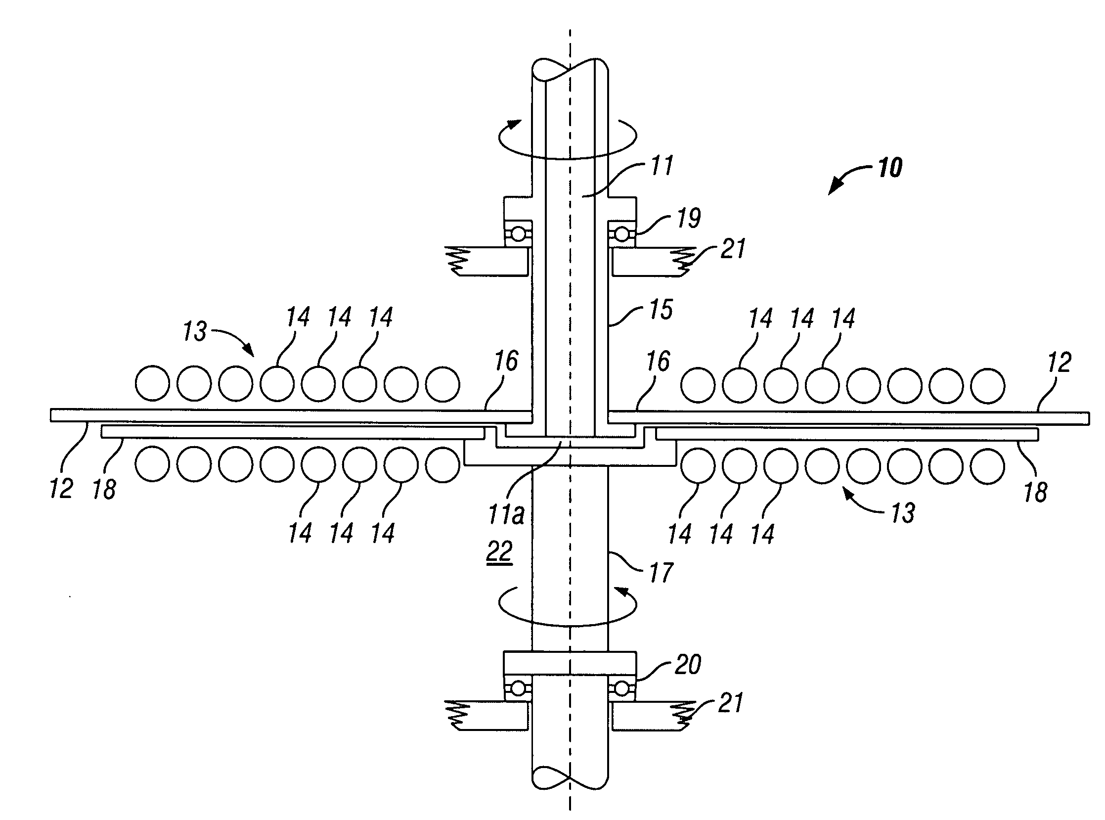
[0037]Referring to FIG. 1 of the drawings, there is shown a fluid disinfection apparatus 10 comprising a central duct 11 for receiving fluid to be disinfected into the apparatus from an inlet thereof. The inlet 11 is formed as a bore of a first drive shaft 15 and is in communication with a pressurised source of fluid to be disinfected. The fluid pressure is controlled by a pressure regulator (not shown); by controlling the pressure of the fluid, a controlled rate of fluid flow can be maintained through the apparatus.

[0038]The distal end of the first drive shaft is secured to the central portion of a first disc 16, with the bore 11 extending through the disc. Adjacent the first drive shaft 15 there is arranged a second drive shaft 17, the distal end of which is secured to the central portion of a second disc 18.

[0039]The first and second drive shafts 15,17 are arranged co-axially with each other. The drive shafts are mounted to bearing sleeves 19 and 20, which permit the drive shafts...


PUM

PropertyMeasurementUnit
relative speedsaaaaaaaaaa
viscousaaaaaaaaaa
transmission coefficientsaaaaaaaaaa

Abstract

An apparatus for disinfecting fluids comprises a thin flow channel 12 which extends between a pair of parallel discs 16,18. The fluid to be treated flows radially of the discs 16,18 through the flow channel 12 where it is irradiated axially of the discs by ultra-violet light emitted by one or more lamps 14. At least one of the discs 16,18 is rotated to cause relative movement therebetween. The relative rotation of the discs 16,18 creates a turbulent flow of fluid within the flow channel 12 to ensure that the fluid circulates and swirls close to the opposed surfaces of the discs, thereby ensuring that all parts of the fluid are exposed to an intense dose of ultra-violet radiation. The thin planar flow channel 12 enables a relatively large volume of fluid to be efficiently disinfected since the ultra-violet radiation can pass axially of the discs 16,18 through the thin fluid layer over the large surface area of the discs 16,18 without suffering from significant UV absorption.

Description

BACKGROUND OF THE INVENTION[0001]1. Field of the Invention[0002]This invention relates to an apparatus for disinfecting fluids and to a method of disinfecting fluids.[0003]2. Related Background Art[0004]It is well known that high intensity ultra-violet (UV) light has germicidal properties that can be used to disinfect liquids; EP0202891 discloses a device which utilises these properties. The germicidal effect of UV light occurs when the UV light is transmitted through the liquid and results in the disruption of the DNA of any micro-organisms within the liquid, thereby killing or inactivating the micro-organisms.[0005]However, the germicidal effect of UV light is dependent on the UV light passing through the water being disinfected. This can be particularly difficult if the water is viscous or contains a lot of waste material, since the UV light can become totally absorbed after penetrating only a short distance. In these circumstances, a large amount of energy is required to produce...

Claims


Application Information

Patent Timeline
Patent Type & Authority Applications(United States)
IPC IPC(8): A61L2/10
CPCA23L3/28C02F2201/3227C02F1/325A61L2/10C02F1/32
Inventor SNOWBALL, MALCOLM ROBERT
Owner GB ENVIRONMENTAL
Why Eureka
Try Eureka