Photocatalytic reactor and methods of use

a photocatalytic reactor and photocatalytic technology, applied in the direction of gravity filters, water treatment compounds, specific water treatment objectives, etc., can solve the problems of limiting the rate of catalytic reaction, affecting the efficiency of photocatalytic reaction, so as to achieve the effect of increasing the amount of gas

Inactive Publication Date: 2013-01-10
CATALYSYST
View PDF9 Cites 12 Cited by
  • Summary
  • Abstract
  • Description
  • Claims
  • Application Information

AI Technical Summary

Benefits of technology

[0076]The method may comprise the step of reducing the temperature of the second liquid to increase the amount of g

Problems solved by technology

The rate of a catalytic reaction may be limited by mass transfer and therefore by the number of reactant molecules brought into contact with an active site of the catalyst.
The rate-limiting effects of mass transfer become particularly prevalent when the concentration of

Method used


Image

  • Photocatalytic reactor and methods of use
  • Photocatalytic reactor and methods of use
  • Photocatalytic reactor and methods of use

Examples


Embodiment Construction

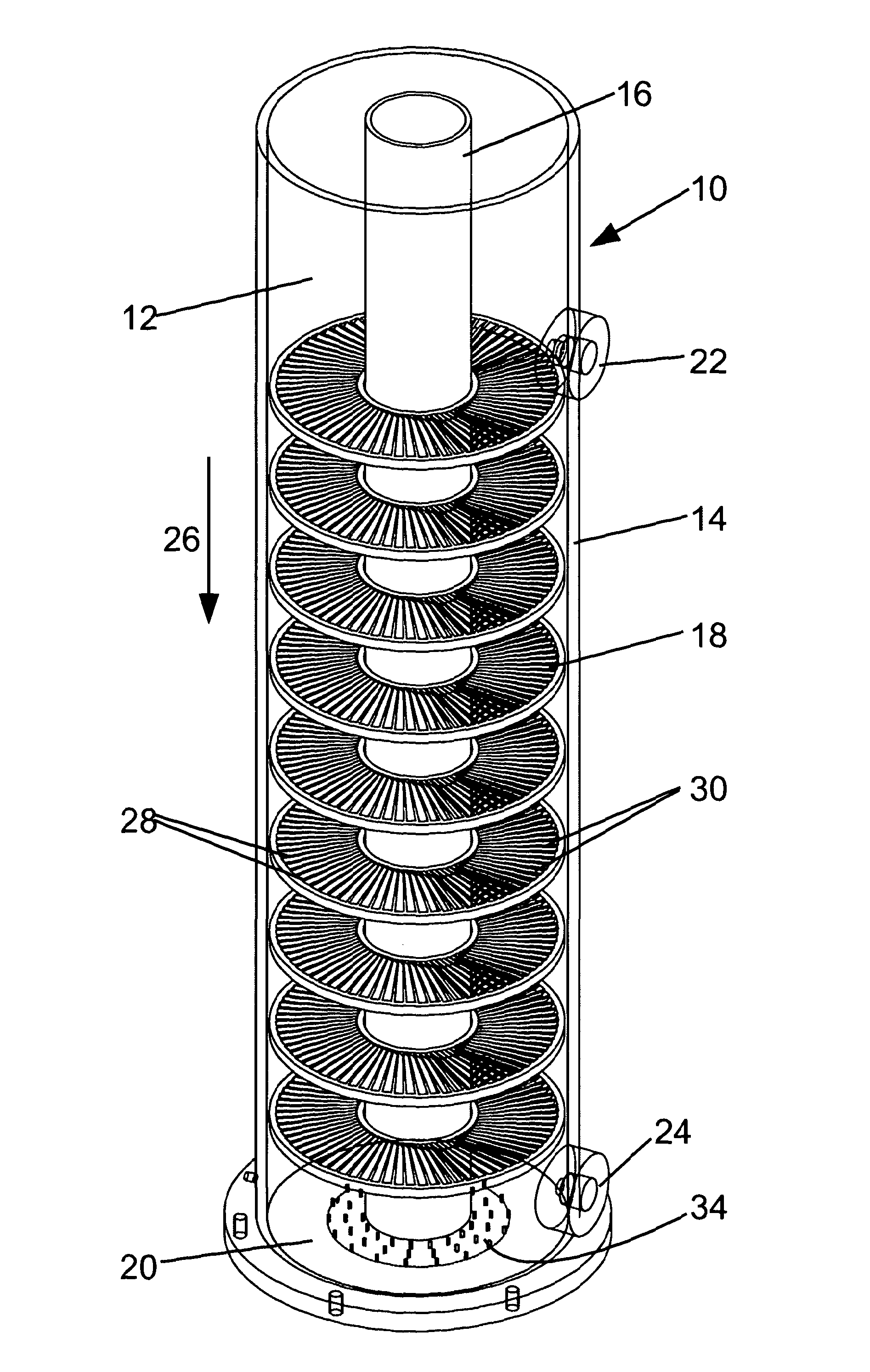
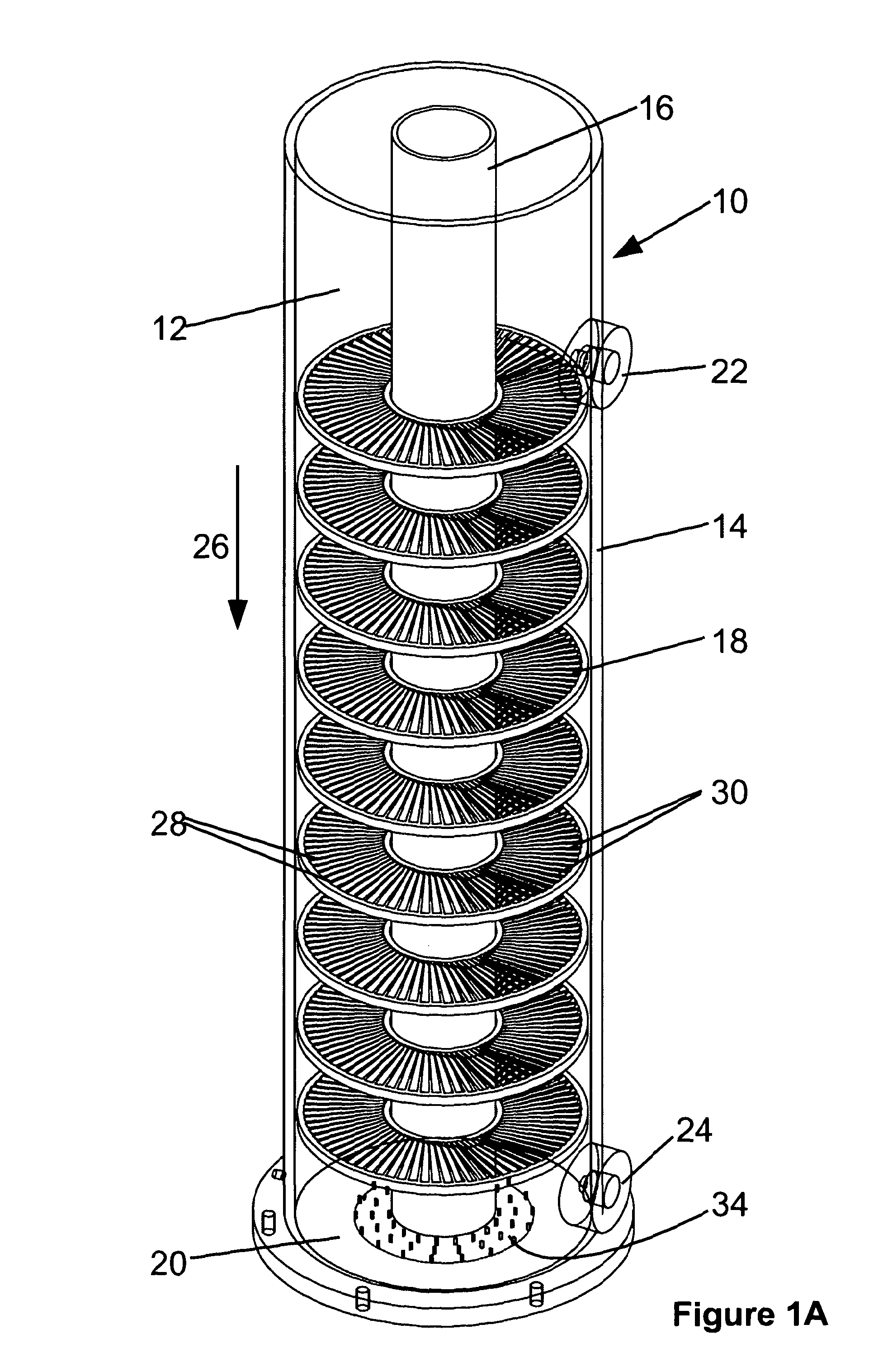
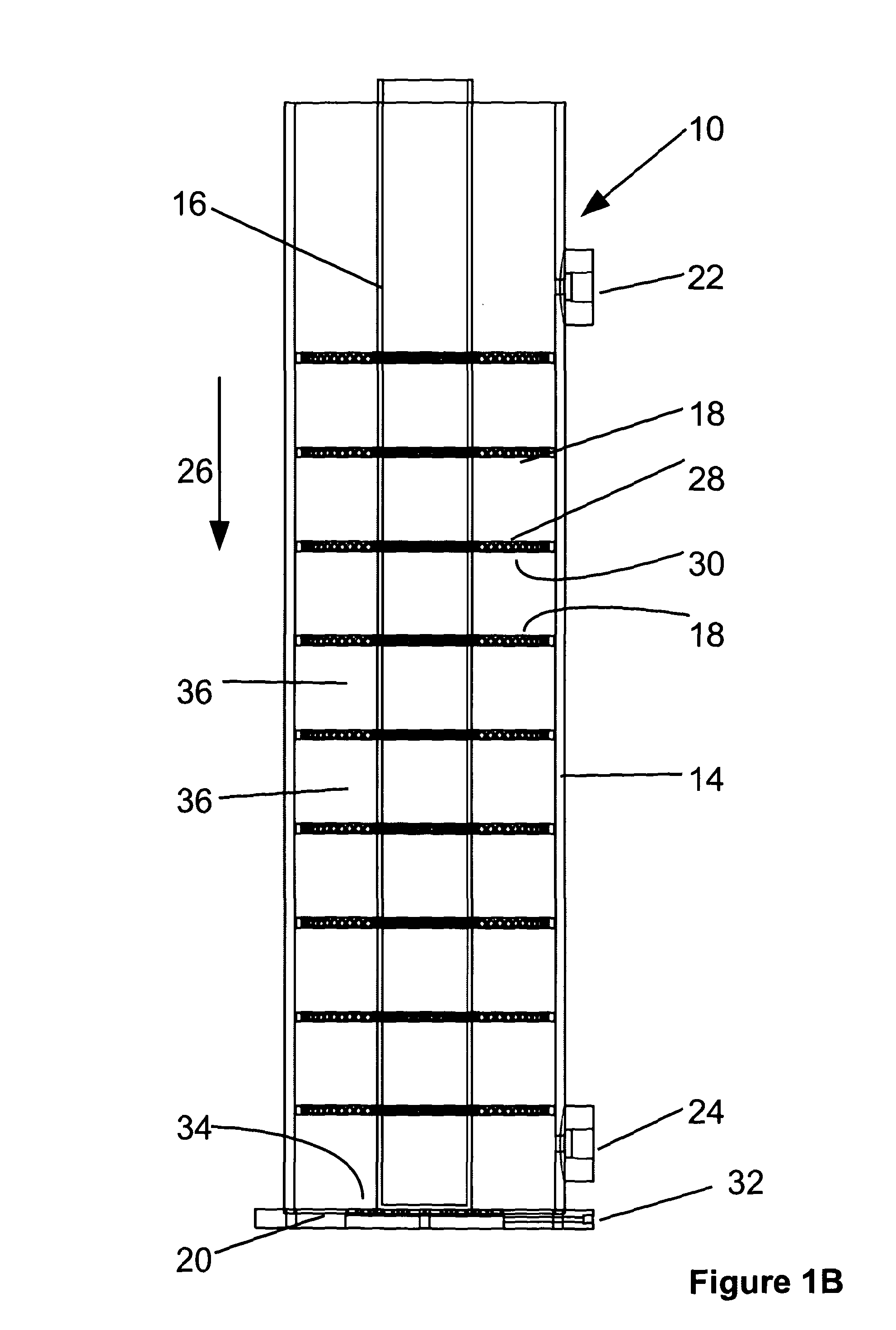
[0109]Referring firstly to FIGS. 1A to 1C, there is shown a reactor 10 in accordance with an embodiment of the invention shown in perspective view, in longitudinal section, and in cross section respectively. The reactor 10 is configured as a photocatalytic reactor and comprises a flow-through reaction chamber 12 defined by a wall 14 and a base plate 20.

[0110]Reactor 10 is well suited to for example the treatment of contaminated wastewater from a variety of industrial processes. Contaminated wastewater from these processes often contains hydrocarbons including glycols, surfactants and other soluble compounds. Due to their solubility these compounds are difficult to remove by traditional treatment methods. It is known that these compounds are amenable to destruction using photocatalytic systems however the reactions are inefficient and are not easily scaled-up to plant size. This embodiment is described in context of wastewater, although it has application to other liquid treatments a...


PUM

PropertyMeasurementUnit
Flow rateaaaaaaaaaa
Lengthaaaaaaaaaa

Abstract

The present invention provides an apparatus and method for carrying out a photocatalytic reaction. The apparatus comprises a reaction chamber having a longitudinal axis and comprising a fluid inlet and a fluid outlet displaced in a longitudinal direction. A bearing surface is provided for a layer of mobile photocatalyst particles disposed between the fluid inlet and the fluid outlet, and a reactant fluid flowing between the fluid inlet and the fluid outlet contacts the layer of mobile photocatalyst particle. A formation is provided to redirect the fluid flow through the layer of mobile photocatalyst particles to increase the contact of the fluid with the layer of mobile photocatalyst particles.

Description

[0001]The present invention relates to photocatalytic reactors and methods of use, and in particular to photocatalytic reactors which use a layer or bed of particulate or granular photocatalyst bodies for the treatment of a fluid. Aspects of the invention relate to the treatment of contaminated wastewater from industrial processes.BACKGROUND TO THE INVENTION[0002]For a heterogeneous catalytic reaction between a solid phase catalyst and liquid phase reactant, the rate of reaction depends on, amongst other things, the exposed surface area of the catalyst and the efficiency of diffusion of molecules of the reactant to and from the surface of the catalyst.[0003]Catalytic reactors are engineered to maximise the yield of product obtained by the chemical reactions for which they are designed. A catalytic reactor typically has a reaction chamber containing a catalyst and the reactant. The rate of a catalytic reaction may be limited by mass transfer and therefore by the number of reactant mo...

Claims


Application Information

Patent Timeline
IPC IPC(8): C02F1/00
CPCB01J19/123B01J2219/0884B01J2219/0892C02F1/325C02F1/74C02F2101/32C02F2305/10C02F2201/008C02F2201/3223C02F2201/3228C02F2201/328C02F2301/026C02F2303/04C02F2103/023B01D43/00B01D53/86B01J8/04B01J8/28B01J19/12C02F1/32C02F1/72
Inventor FOSTER, NEIL
Owner CATALYSYST
Why Eureka
Try Eureka