Non-invasive blood component measuring device and non-invasive blood component measuring method

Inactive Publication Date: 2009-01-01
SYSMEX CORP
View PDF3 Cites 15 Cited by
  • Summary
  • Abstract
  • Description
  • Claims
  • Application Information

AI Technical Summary

Benefits of technology

[0008]A first aspect of the present invention is, a non-invasive blood component measuring device comprising: a light source section for irradiating a light to a blood vessel through a skin; an imaging section for imaging the irradiated blood vessel through the skin; and a controller, including a memory under control of a processor, the memory storing instructions enabling the processor to carry out operations, comprising: creating a concentration profile based on an image obtained by imaging the blood vessel with the imaging section; calculating a blood component concentration based on the concentration profile; acquiring a shape feature of the concentration profile; and correcting the blood component concentration based on th

Problems solved by technology

However, the cross section of the blood vessel is not necessarily always a perfect circle, and sometimes deforms due to various reasons.
If the external temperature is low or depending on the bend of the wrist in time of measurement, or if the peripheral blood vessel has disability, the blood flow volume tends to become insufficient, whereby the blood vessel constricts and the cross section of the blood vessel deforms.

Method used


Image

  • Non-invasive blood component measuring device and non-invasive blood component measuring method
  • Non-invasive blood component measuring device and non-invasive blood component measuring method
  • Non-invasive blood component measuring device and non-invasive blood component measuring method

Examples


first embodiment

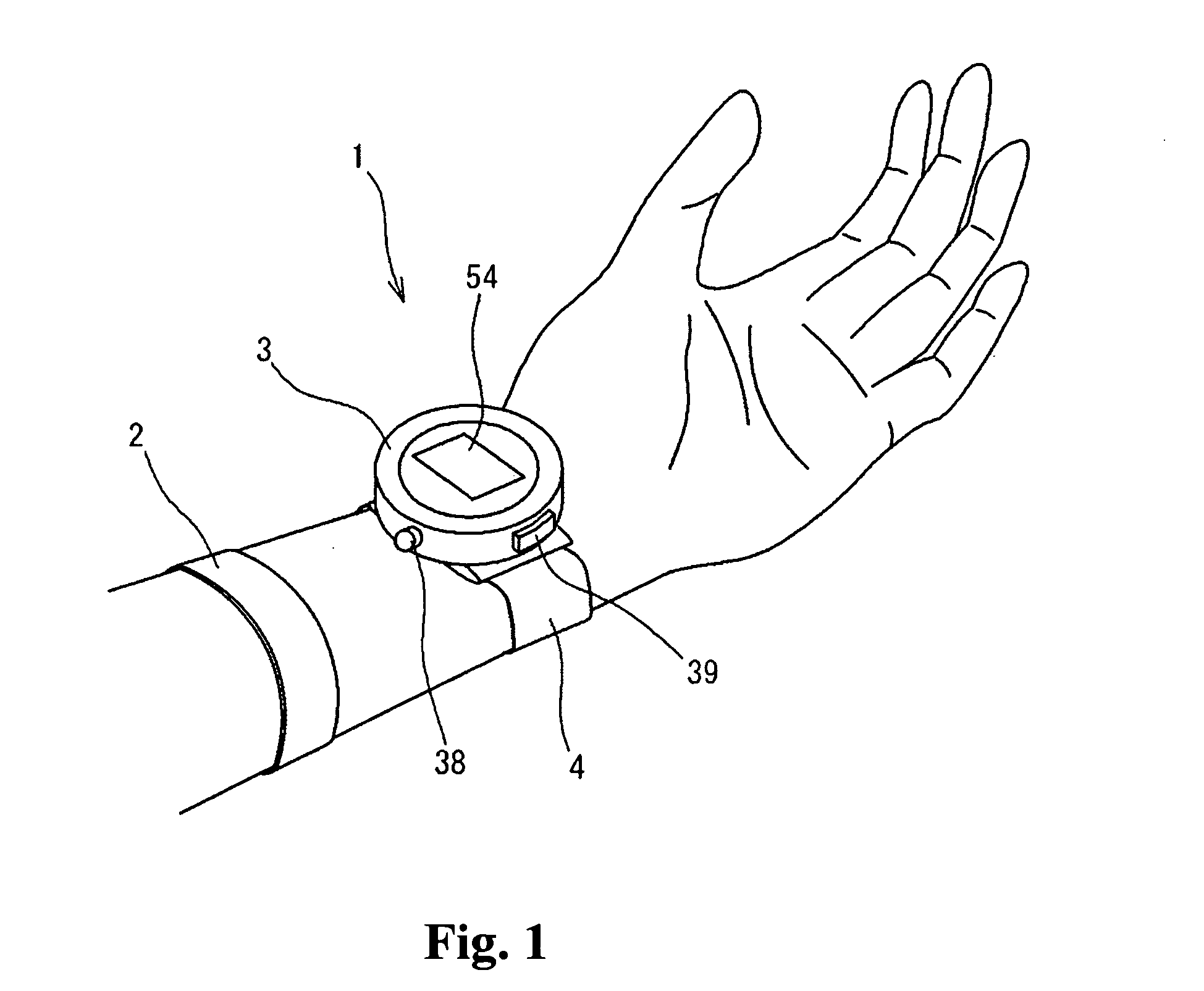
[0035]FIG. 1 shows a schematic configuration of a non-invasive blood component measuring device 1 according to the present invention. The non-invasive blood component measuring device 1 is a wrist watch type device and includes a device body 3 and a holder 4. The device body 3 is attached to the wrist of a human by means of the holder 4. The device body 3 is attached in a position adjustable manner in a peripheral direction of the wrist by means of the holder 4. A power / execute key 38 and a menu key 39 for enabling the user to operate the non-invasive blood component measuring device 1 are arranged on the side face of the device body 3. A pressurization band 2 (cuff) is attached to the arm of the user closer to the heart than the wrist. The pressurization band 2 pressurizes the arm of the user at a predetermined pressure to inhibit the blood flow near the wrist, thereby dilating the blood vessel (vein) of the wrist. Thus, the imaging of the blood vessel is facilitated by making the ...

second embodiment

[0118]If formula (17) is used, the hemoglobin concentration D0′ is given based on the cross sectional area of the blood vessel. Since the cross sectional area of the blood vessel is always constant even if the shape of the blood vessel changes, an accurate hemoglobin concentration non-dependent on the change in the blood vessel cross sectional shape can be calculated. As a still variant of the second embodiment, the formula (17) may be used in step S118 of the flowchart shown in FIG. 21.


PUM


Abstract

A non-invasive blood component measuring device comprising: a light source section for irradiating a light to a blood vessel through a skin; an imaging section for imaging the irradiated blood vessel through the skin; and a controller, including a memory under control of a processor, the memory storing instructions enabling the processor to carry out operations, comprising: creating a concentration profile based on an image obtained by imaging the blood vessel with the imaging section; calculating a blood component concentration based on the concentration profile; acquiring a shape feature of the concentration profile; and correcting the blood component concentration based on the shape feature of the concentration profile is disclosed. A non-invasive blood component measuring method is also disclosed.

Description

RELATED APPLICATIONS[0001]This application claims priority under 35 U.S.C. §119 to Japanese Patent Application No. JP2007-171875 filed Jun. 29, 2007, the entire content of which is hereby incorporated by reference.FIELD OF THE INVENTION[0002]The present invention relates to a non-invasive blood component measuring device and a non-invasive blood component measuring method for percutaneously measuring a blood component to be measured without drawing blood from a living body.BACKGROUND[0003]A method and a device for non-invasively measuring hemoglobin concentration without drawing blood from a subject have been conventionally proposed. U.S. Pat. No. 6,061,583 Publication discloses a device for illuminating a living body tissue including blood vessels with a light source and imaging a transmitted light image, extracting an image concentration distribution distributed across the blood vessel from the imaged image as a concentration profile of the image, cutting out a portion correspondi...

Claims


Application Information

Patent Timeline
IPC IPC(8): A61B5/1455
CPCA61B5/681A61B5/1455
Inventor OZAWA, TOSHIYUKINUMADA, SHIGEHIRO
Owner SYSMEX CORP
Why Eureka
Try Eureka