Mri-safe defibrillator electrodes

a defibrillator and electrode technology, applied in the field of defibrillator electrodes, can solve the problems that the requirements of defibrillator systems create unique challenges, and achieve the effect of reducing patient risks and reducing patient risks

Inactive Publication Date: 2009-01-01
MEDTRONIC INC
View PDF31 Cites 27 Cited by
  • Summary
  • Abstract
  • Description
  • Claims
  • Application Information

AI Technical Summary

Benefits of technology

[0007]One aspect of the present invention utilizes a self-healing dielectric material that prevents induced voltages from MRI equipment from damaging an ICD or causing unintended defibrillation shocks to a patient thereby reducing patient risks associated with RF-induced thermogenic tissue damage and with pulsed gradient-field-

Problems solved by technology

However, the specific characteristics and requirements of defibrillator systems create unique challenges.
While this may occur very rarely, prior art solutions to thermogenic tissue risks associated with the

Method used


Image

  • Mri-safe defibrillator electrodes
  • Mri-safe defibrillator electrodes
  • Mri-safe defibrillator electrodes

Examples


Embodiment Construction

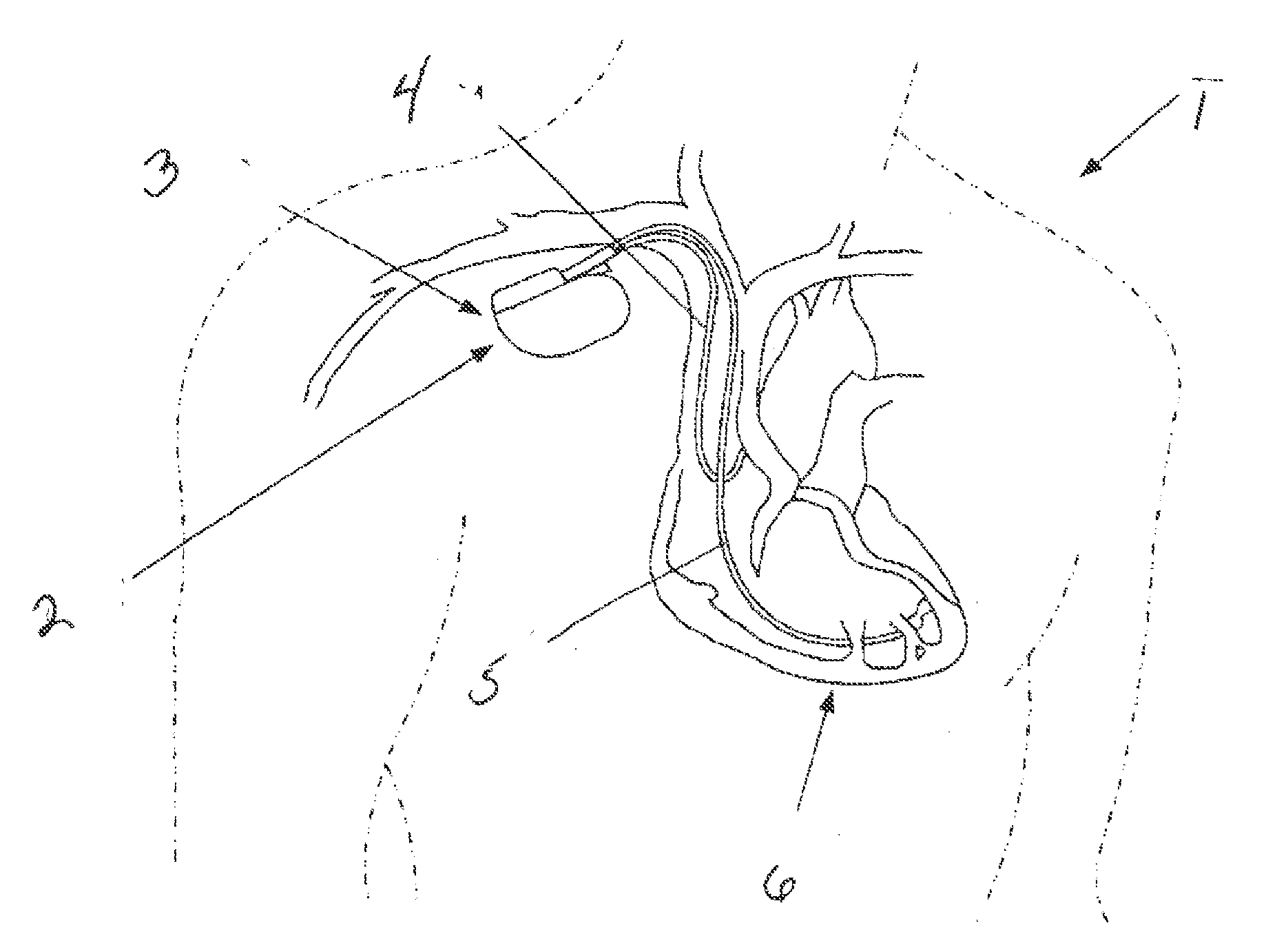
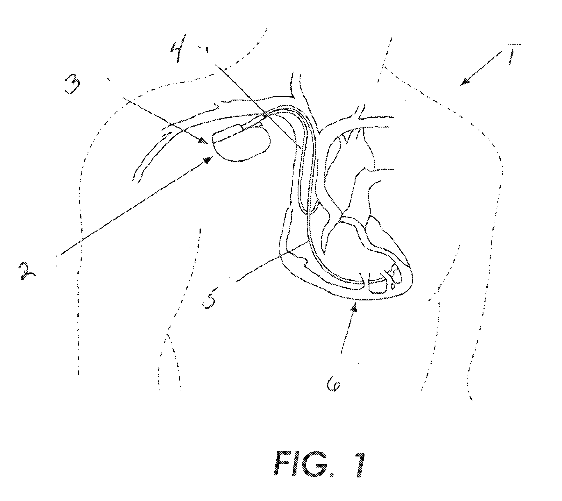
[0012]FIG. 1 illustrates a patient 1 having a cardioverter defibrillator 2 implanted in the right shoulder area 3. A lead 4 is shown extending into the right atria of the patients heart 6, while another lead 5 is shown extending into the right ventricle of the heart 6. The ventricular lead 5 comprises a pacing / defibrillation lead capable of pacing the heart 6 in the event an intrinsic heart beat is not detected. The lead 5 can also deliver a defibrillation pulse (shock) to the patient in the event that the defibrillator 2 determines that a life threatening arrhythmia is detected.

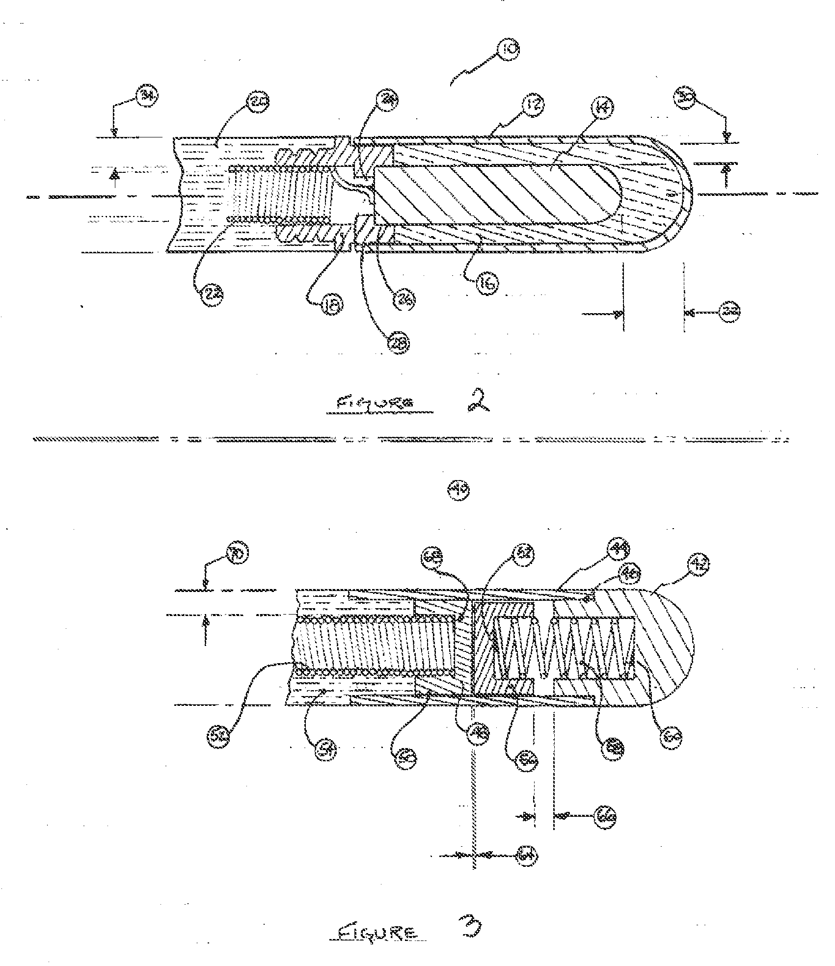
[0013]FIG. 2 shows a preferred embodiment of the tip of the defibrillator lead 15 that uses a self-healing dielectric material, such as disclosed in published US Patent Application, publication number 2006-0271138A1, entitled Electromagnetic Interference Immune Pacing / Defibrillation Lead. Published US Patent Application, publication number 2006-0271138A1, describes various means to employ self-healing dielec...


PUM


Abstract

The present invention reduces patient risks associated with RF-induced thermogenic tissue damage and with pulsed gradient-field-induced arrhythmias by using a defibrillator lead having a self-healing dielectric material that prevents induced voltages from MRI equipment from damaging an ICD or causing unintended defibrillation shocks to a patient. Another aspect of the present invention utilizes a sliding contact arrangement to prevent induced voltages from MRI equipment from being electrically coupled to an ICD thereby reducing patient risks associated with RF-induced thermogenic tissue damage and with pulsed gradient-field-induced arrhythmias.

Description

CROSS-REFERENCE TO RELATED APPLICATION[0001]This application claims the benefit of U.S. Provisional Application No. 60 / 946,411 filed Jun. 27, 2007.FIELD OF THE PRESENT INVENTION[0002]The present invention is directed to a defibrillator electrode. More particularly, the present invention is directed to a defibrillator electrode that can be used in a magnetic resonance imaging environment.BACKGROUND OF THE PRESENT INVENTION[0003]Various approaches have been taken to reduce or eliminate the risks associated with patients having implanted medical devices who need magnetic resonance imaging (MRI) examinations.[0004]However, the specific characteristics and requirements of defibrillator systems create unique challenges. Unlike pacemaker, drug pump, and neurostimulation devices, implantable cardioverter defibrillators (ICDs) not only sense and pace the heart in a manner similar to a pacemaker, but also may release electrical energy in pulses of up to 40 Joules and at an excess of 800 volts...

Claims


Application Information

Patent Timeline
IPC IPC(8): A61N1/39
CPCA61N2001/086A61N1/0563A61N1/086
Inventor MACDONALD, STUART G.
Owner MEDTRONIC INC
Why Eureka
Try Eureka