Efficient Computation Method for Electromagnetic Modeling

a computation method and electromagnetic modeling technology, applied in the field of geophysical prospecting, can solve the problems of losing the advantages of the frequency domain method in time domain analysis in the deep water case, the computational task of simulation of electromagnetic fields is very demanding, and the cost of csem is computationally even more expensive than the frequency domain method

Active Publication Date: 2009-01-01
EXXONMOBIL UPSTREAM RES CO
View PDF7 Cites 65 Cited by
  • Summary
  • Abstract
  • Description
  • Claims
  • Application Information

AI Technical Summary

Problems solved by technology

Time domain solutions to CSEM exist but are computationally even more costly than frequency domain methods.
Although they offer clear advantages in handling the so-called air wave effect in land or shallow water surveys (the air wave is the direct transmission from the broadcasting antenna to the detecting antenna through the air), time domain analysis in the deep water case loses the advantages of the frequency domain method because the time domain response is spread across frequencies of little interest to hydrocarbon exploration for targets at typical reservoir depths.
Unfortunately, the extreme accuracy of the data also makes simulation of the electromagnetic fields a very demanding computational task.
Unfortunately, IE methods appear to be poorly suited for modeling applications when the models exhibit significant variations nearly everywhere, as is expected in the hydrocarbon exploration case.
An additional disadvantage of the IE method is that direct discretization of the integral equations gives rise to systems of equations which are highly non-sparse (the electric field unknowns obey equations for which all terms contribute).
Unfortunately, the equations of the FDFD method need to be solved for each frequency of interest and for each of the many thousands of transmitter positions occupied by the broadcasting antenna used in an actual survey.
While the possibility exists that some method along these lines might be made to work, the present inventors have experimented several times with this procedure and found that correcting solutions from nearby transmitter locations is just as expensive as obtaining independent solutions for all transmitter locations when seeking solutions that reflect the high accuracy observed in the actual measured data.
Unfortunately, the computational cost of such decompositions is of order (3N)3 making this approach too costly for 3-D models, but possibly affordable for 2-D models for which N will be approximately 100 times less than in 3-D (and therefore one million times less expensive for a decomposition because the cost is cubic in N).
Experiments with using nearby transmitter solutions as the starting point for iterative solutions demonstrate that the effective spectral radius (the range of significant singular values in D) required for accurate electric field solutions may be extremely broad so that this approximate approach may not be cost effective.
A further difficulty in the complete decomposition approach is that the most widely used mathematical algorithms do not lend themselves to a parallel implementation.

Method used


Image

  • Efficient Computation Method for Electromagnetic Modeling
  • Efficient Computation Method for Electromagnetic Modeling
  • Efficient Computation Method for Electromagnetic Modeling

Examples


case p (

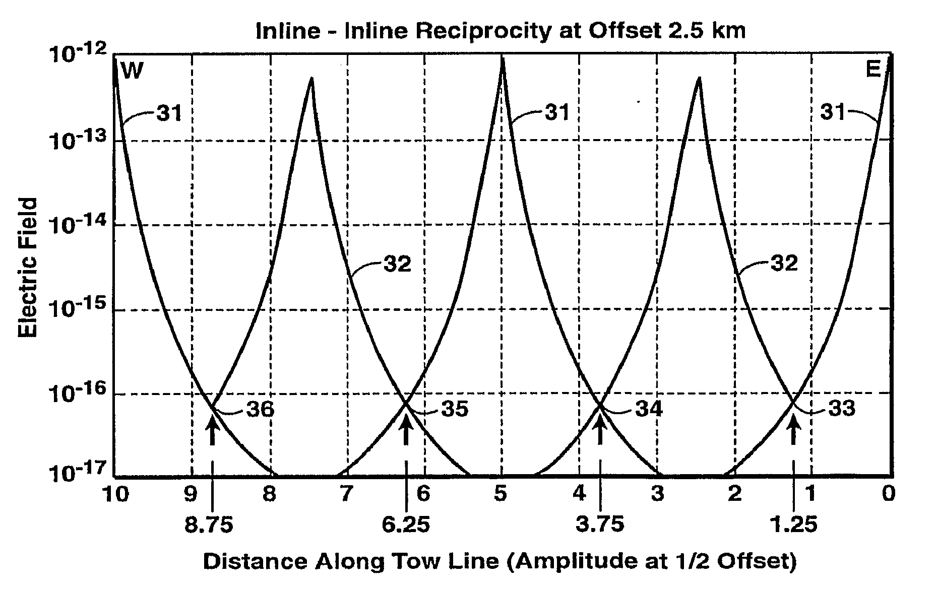
[0073]FIG. 4 shows results for stations at the 0, 5, and 10 km positions for antennas with vertical orientation. The data for the 5-km station are taken from the reciprocal experiment, so that the field values for the primary and reciprocal surveys should again be equal at the 2.5 km and at the 7.5 km positions (again indicated by vertical arrows). Three sets of curves are plotted over each other in this figure, representing results from different mesh interpolation techniques. The inset magnification 41 around one of the expected reciprocal points (˜7.5 km) shows varying degrees of success in honoring the Reciprocity Principle; again, numerical results are presented in the tables below. The three cases having deviations from reciprocal behavior shown with double-headed arrows labeled O, L, and P are described as follows:[0074]Case O (“original”) uses the original mesh, with coarse uniform spacing in the X and Y directions. This case (with the two bold dashed curves) has the largest...


PUM


Abstract

Method for efficient processing of controlled source electromagnetic data, whereby Maxwell's equations are solved [107] by numerical techniques [109] such as finite difference or finite element in three dimensions for each source location and frequency of interest. The Reciprocity Principle is used [103] to reduce the number of computational source positions, and a multi-grid is used [105] for the computational grid to minimize the total number of cells yet properly treat the source singularity, which is essential to satisfying the conditions required for applicability of the Reciprocity Principle. An initial global resistivity model [101] is Fourier interpolated to the computational multi grids [106]. In inversion embodiments of the invention, Fourier prolongation is used to update [120] the global resistivity model based on optimization results from the multi-grids.

Description

[0001]This application claims the benefit of U.S. Provisional Application No. 60 / 780,232 filed on Mar. 8, 2006.FIELD OF THE INVENTION[0002]This invention relates generally to the field of geophysical prospecting, and more particularly to controlled source electromagnetic surveys exploring for oil and gas deposits located beneath the ocean. Specifically, the invention is a method for performing the Maxwell equation solutions required for full 2-D or 3-D modeling and / or inversion of controlled source electromagnetic survey data to reveal resistivity anomalies in subsurface formations.BACKGROUND OF THE INVENTION[0003]The offshore environment, particularly in the deep water case, offers a combination of unique circumstances that make the application of exploration methods based upon remote measurements of electrical resistivity a useful and cost effective exploration tool. These circumstances are:[0004]1. The high cost of offshore exploration wells.[0005]2. The very low level of electri...

Claims


Application Information

Patent Timeline
Patent Type & Authority Applications(United States)
IPC IPC(8): G06G7/48
CPCG01V3/12G01V3/083G06G7/48G16Z99/00
Inventor CARAZZONE, JAMES J.CLEE, T. EDWARD
Owner EXXONMOBIL UPSTREAM RES CO
Why Eureka
Try Eureka