Apparatus and method for detecting cam phase of engine
- Summary
- Abstract
- Description
- Claims
- Application Information
AI Technical Summary
Benefits of technology
Problems solved by technology
Method used
Image

Examples
Embodiment Construction
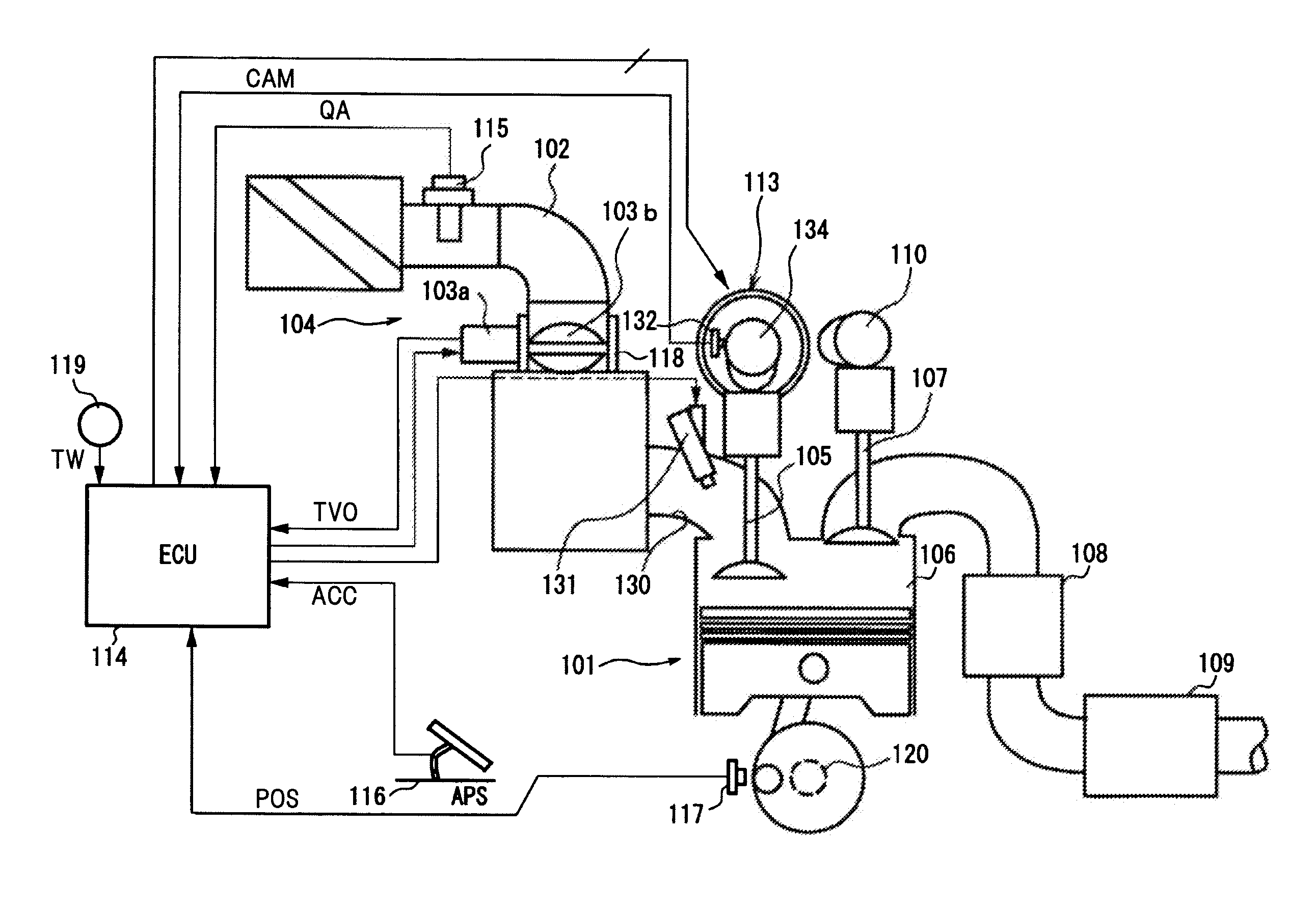
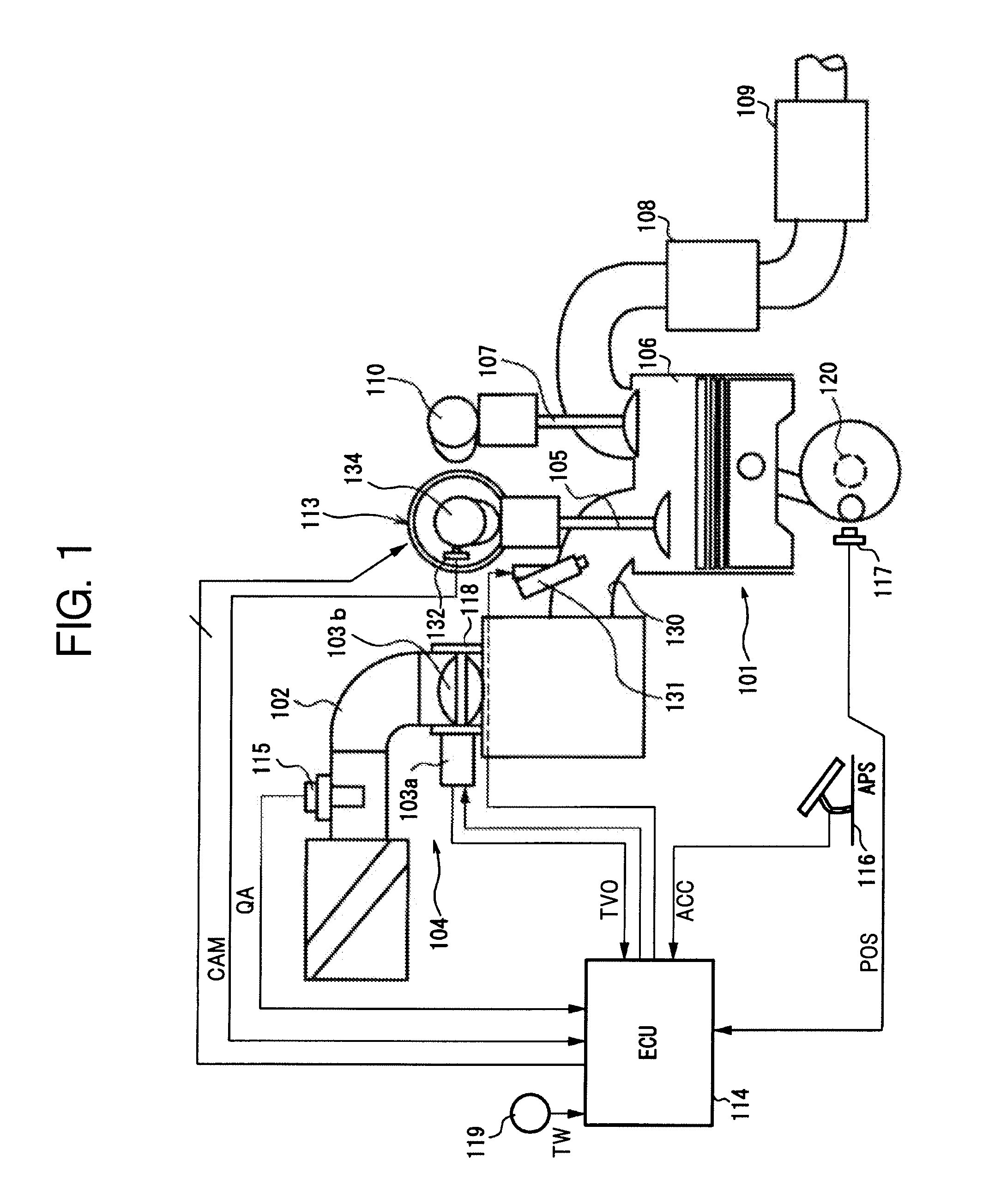
[0044]FIG. 1 is a block diagram of a four-cylinder gasoline engine.
[0045]In FIG. 1, in an intake pipe 102 of an engine 101, an electronically controlled throttle 104 for driving opening or closing of a throttle valve 103b by the use of a throttle motor 103a is disposed.
[0046]Then, an introduction of air by suction into a combustion chamber 106 is carried out via electronically controlled throttle 104 and an intake valve 105.
[0047]An electromagnetic fuel injection valve 131 is disposed at an intake port 130 of each cylinder.
[0048]Fuel injection valve 131 is driven to open based on an injection pulse signal from an ECU (engine control unit) 114, to inject fuel regulated at a predetermined pressure toward intake valve 105.
[0049]The fuel introduce by suction into combustion chamber 106 is combusted by spark-ignition conducted by an ignition plug (not shown in the figure).
[0050]The gas having combusted in combustion chamber 106 is exhausted from this combustion chamber to an exhaust pipe...
PUM
 Abstract
Description
Claims
Application Information