Air intake device for multi-cylinder internal combustion engine

Inactive Publication Date: 2009-01-08
TOYOTA JIDOSHA KK
View PDF0 Cites 3 Cited by
  • Summary
  • Abstract
  • Description
  • Claims
  • Application Information

AI Technical Summary

Benefits of technology

[0018]The present invention has been made to solve the foregoing problems and it is an object of the present invention to provide an air int

Problems solved by technology

This poses a problem in that the wavy portion of the funnel 101 disturbs an air flow to produce intake resistance, leading to reduced air intake efficiency.
Another problem is that, for want of a sufficient space for the funnel 101 of each intake branch pipe, part of the funnel 101 of each intake branch pipe is lost at portions indicated by an arrow B an

Method used


Image

  • Air intake device for multi-cylinder internal combustion engine
  • Air intake device for multi-cylinder internal combustion engine
  • Air intake device for multi-cylinder internal combustion engine

Examples


Example

First Embodiment

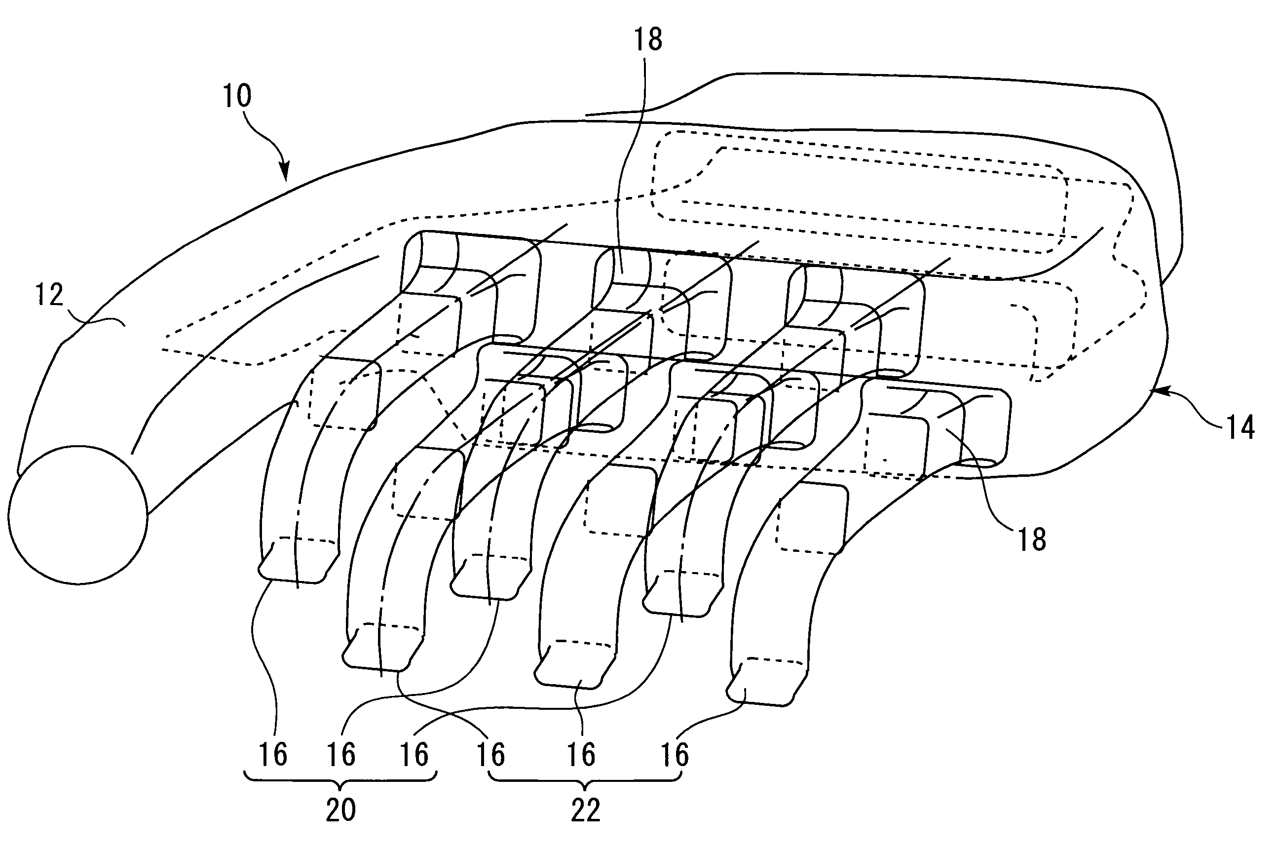
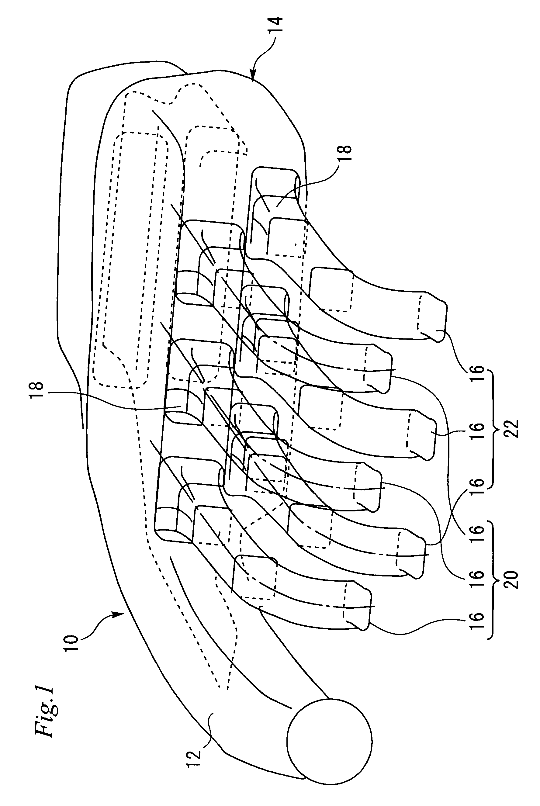
[0035]FIG. 1 is a perspective view showing an air intake device according to a first embodiment of the present invention. Referring to FIG. 1, an air intake device 10 according to the first embodiment of the present invention is for a V-type 6-cylinder engine, comprising an air collector 12 and a surge tank 14 disposed to continue from the air collector 12. Six intake branch pipes 16 for supplying air to cylinders of the V-type 6-cylinder engine are protruded from a side surface of the surge tank 14. A funnel 18 is formed at a portion of each intake branch pipe 16 adjacent the surge tank 14. Each of the intake branch pipes 16 and the funnels 18 have a rectangular transverse cross-sectional shape (shape of a cross section perpendicular to a longitudinal direction).

[0036]Of the six intake branch pipes 16, three constitute a first intake manifold 20 supplying air to cylinders on a first bank of the V-type 6-cylinder engine (hereinafter referred to simply as “engine”) an...


PUM


Abstract

An air intake device includes: a surge tank 14 having an internal space divided into a first space and a second space; a first intake manifold 20 including a plurality of intake branch pipes 16 protruding from the surge tank 14 via a funnel 18 and communicating with the first space, the first intake manifold 20 supplying air to cylinders on a first of two cylinder banks; and a second intake manifold 22 including a plurality of intake branch pipes 16 protruding from the surge tank 14 via the funnel 18 and communicating with the second space, the second intake manifold 22 supplying air to cylinders on a second of the two cylinder banks. The funnel 18 has a substantially rectangular transverse cross-sectional shape.

Description

BACKGROUND OF THE INVENTION[0001]1. Field of the Invention[0002]The present invention relates to an air intake device for a multi-cylinder internal combustion engine.[0003]2. Background Art[0004]In air intake devices of V-type engines, a widely used arrangement includes an integrated surge tank for left and right banks disposed upwardly of the engine. FIG. 7 is a cross-sectional view showing a typical arrangement of such an air intake device for a V-type engine. Referring to FIG. 7, the air intake device includes a first intake manifold 102 and a second intake manifold 104, each having a plurality of intake branch pipes protruding from a surge tank 100 via a funnel 101. The first intake manifold 102 is connected to a first bank of the V-type engine, while the second intake manifold 104 is connected to a second bank of the V-type engine. The surge tank 100 has an internal space that is divided into an upper space 106 and a lower space 108. The first intake manifold 102 is in communic...

Claims


Application Information

Patent Timeline
IPC IPC(8): F02M35/104
CPCF02B27/02F02B27/0252F02B27/0284Y02T10/14F02M35/10065F02M35/116Y02T10/146F02M35/10045F02B27/021F02B27/0242F02B27/0273Y02T10/12
Inventor ABE, KAZUYOSHI
Owner TOYOTA JIDOSHA KK
Why Eureka
Try Eureka