Air cleaner and air intake structures for low-deck vehicle

Inactive Publication Date: 2006-08-22
HONDA MOTOR CO LTD
View PDF2 Cites 18 Cited by
  • Summary
  • Abstract
  • Description
  • Claims
  • Application Information

AI Technical Summary

Benefits of technology

[0021]In another embodiment, a low-deck vehicle comprising an engine shaped like a letter V in the fore-and-aft direction suspended by an upper frame extending from a head pipe rearward and downward and a down frame extending from the head pipe downward, and an air intake structure including air intake connecting hoses and an air cleaner disposed above the engine shaped like a letter V in the fore-and-aft direction, wherein the air intake connecting hoses are disposed between V-shaped banks of the V-shape engine, and disposed substantially along the upper frame and the down frame. Since the air intake connecting hoses are disposed between the V-shaped banks of the V-shape engine suspended from the diamond-shaped vehicle body frame, and disposed substantially along the upper frame and the down frame of the diamond shaped vehicle body frame, the air intake connecting hoses may be disposed substantially linearly. Air may be supplied smoothly from the respective air intake connecting hoses to the respective cylinders by employing the substantially linear air intake connecting hoses. As a consequence, air intake efficiency may further be improved, and the output performance of the V-shape engine may further be improved.
[0022]In addition, in this arrangement, the space inside the vehicle body frame can be utilized effectively to achieve compact arrangement, flexibility in designing may be increased, and the appearance of the low-deck vehicle may be improved. In addition, ease of straddling the vehicle body frame when the driver rides on the vehicle is improved.
[0023]Between the upper frames and the down frames facing the sides of the respective air intake connecting hoses are of a trussed frame structure. Since between the upper frames and the down frames facing the sides of the respective air intake connecting hoses are of a trussed frame structure, rigidity of the res

Problems solved by technology

Therefore, it is not easy to secure a large space th

Method used


Image

  • Air cleaner and air intake structures for low-deck vehicle
  • Air cleaner and air intake structures for low-deck vehicle
  • Air cleaner and air intake structures for low-deck vehicle

Examples


Embodiment Construction

[0055]Referring now to the attached drawings, embodiments of the present invention will be described. Terms “front”, “rear”, “left”, “right”, “up” and “down” represent directions viewed from a driver, and Fr designates the front, Rr represents the rear, L represent the left side, R represents the right side, and CL represents the center of the width of the vehicle (center of the vehicle body). The drawings are to be viewed in the direction in which the reference numerals are oriented in the right way.

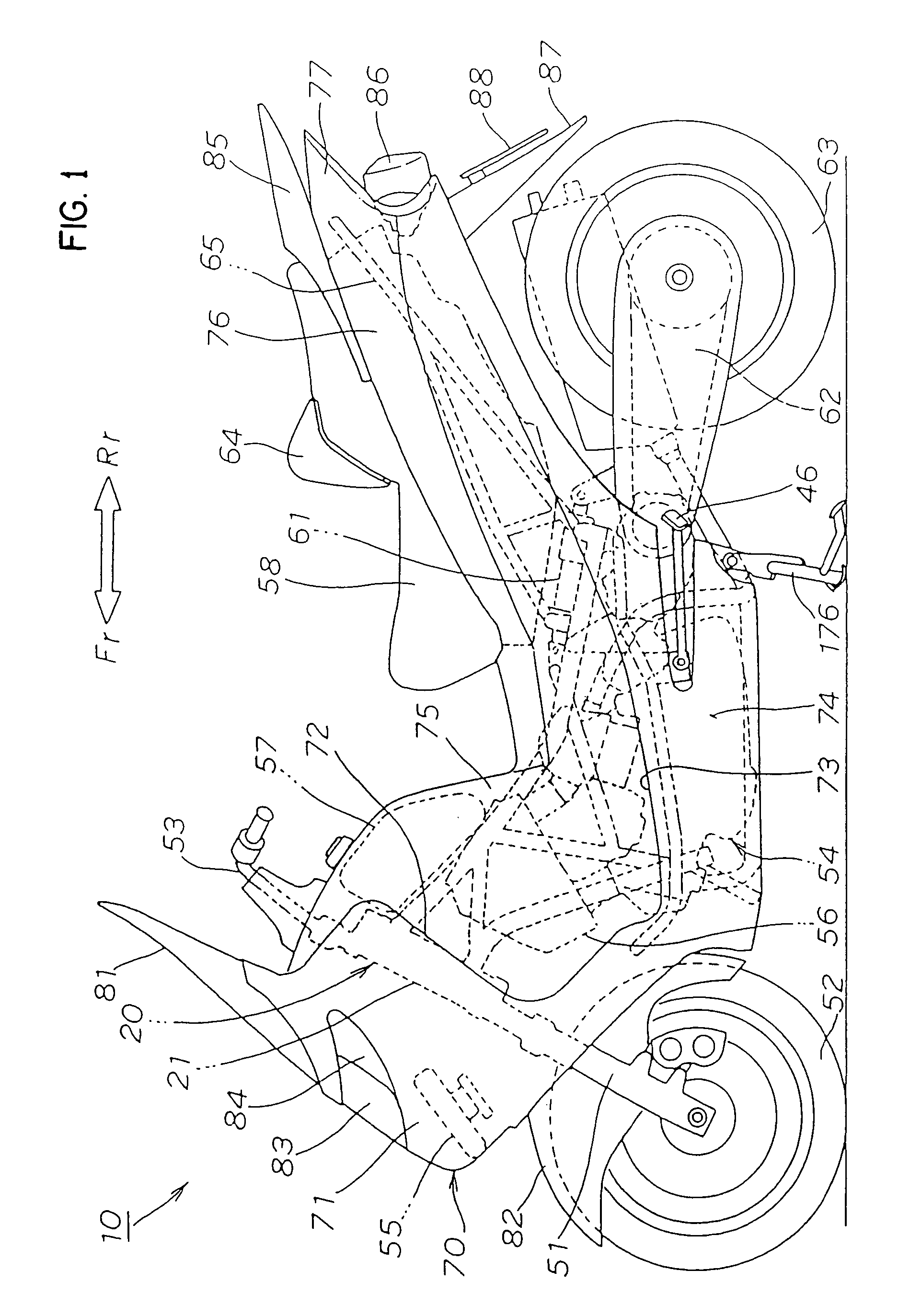
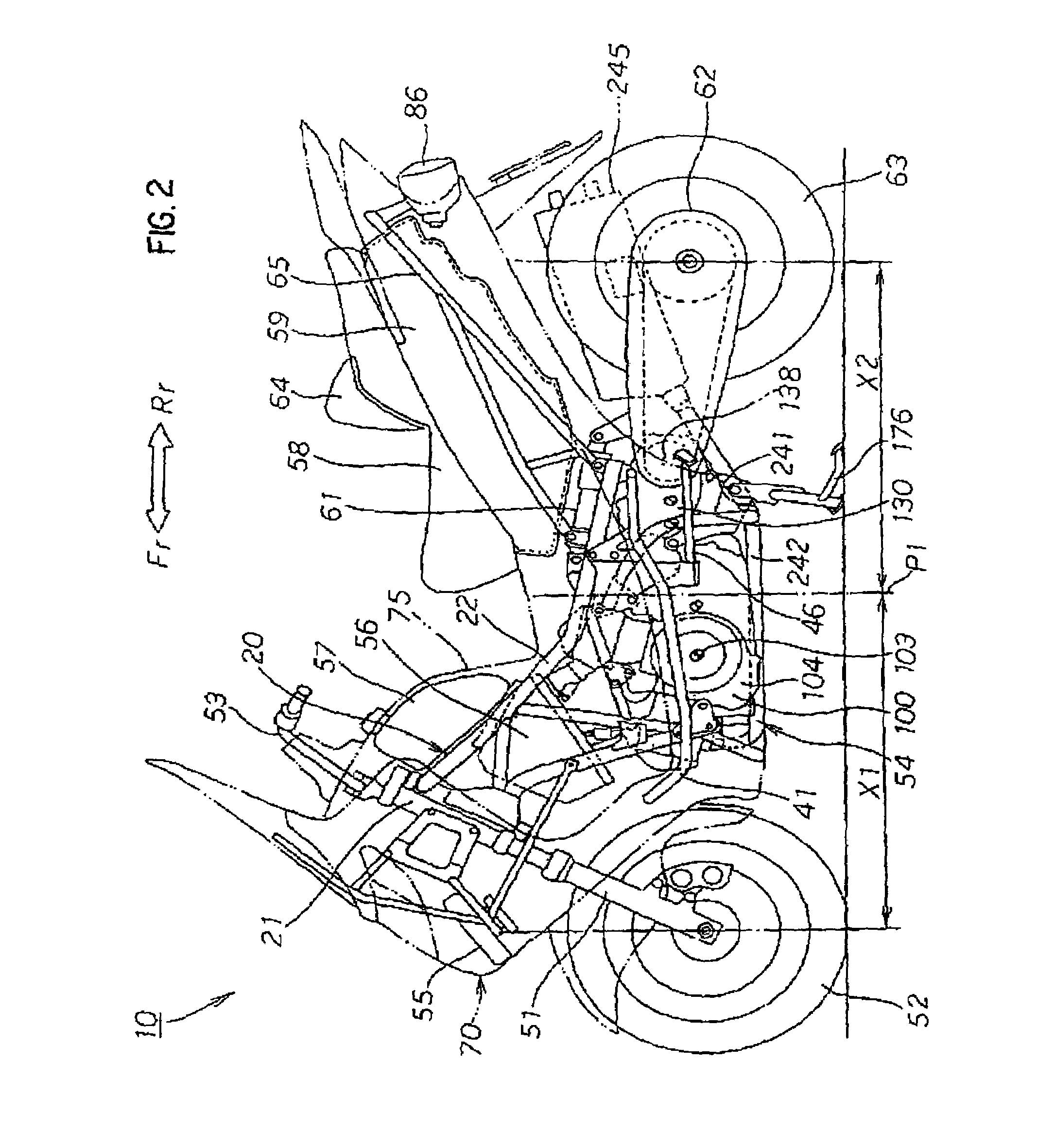
[0056]The general construction of the low-deck vehicle 10 will be described. FIG. 1 is a left side view of a low-deck vehicle according to the present invention (first view), showing a state in which a vehicle body cover is mounted. FIG. 2 is a left side view of the low-deck vehicle according to the present invention (second view), showing a state in which the vehicle body cover is removed. FIG. 3 is a plan view of the low-deck vehicle according to the present invention, in a state in w...


PUM


Abstract

To secure a large space that can be utilized effectively above an air cleaner, a low-deck vehicle 10 is constructed to mount an engine shaped like a letter V in the fore-and-aft direction under a low-deck and an air cleaner. The air cleaner is adapted to be capable of being maintained and inspected from the side of the vehicle. A filter element is provided in the air cleaner, and is attachable and detachable by a lid member on the side of the air cleaner. An inspection lid opposing the lid member is provided on a vehicle body cover covering the air cleaner. A space for arranging vehicle accessories such as a fuel tank is provided above the air cleaner.

Description

FIELD OF THE INVENTION[0001]The present invention relates to an air cleaner structure and an air intake structure of an engine for a low-deck vehicle.BACKGROUND OF THE INVENTION[0002]In a low-deck vehicle such as a scooter-type motor cycle or motor tricycle, a technology in which an engine shaped like a letter V in the fore-and-aft direction is mounted at the lower portion of a vehicle body frame, and an air intake structure and an air cleaner structure are disposed above the engine is disclosed in JP-A-2001-88763. FIG. 28 is a schematic drawing of a low-deck vehicle which corresponds to FIG. 2 in JP-A-2001-88763. Parts shown therein are renumbered.[0003]The low-deck vehicle 300 is a scooter-type motorcycle in which a power unit 320 is mounted in a double-cradle type vehicle body frame 310 at the position downwardly of a low-deck 318.[0004]The vehicle body frame 310 includes a pair of left and right upper frames 312, 312 (only the left one is shown, hereinafter) extending from a hea...

Claims


Application Information

Patent Timeline
IPC IPC(8): B01D35/30F01P7/10F02M35/10B62K11/00B62K11/10F01P3/18F02B61/02F02B75/18F02B75/22F02M35/04F02M35/16
CPCB62K11/10F02B61/02F02B75/22F02M35/162F02M35/04F02M35/10039F02M35/10098F02M35/10216F02M35/116B62K2202/00F01P3/18F01P2050/16F02B2075/1808F02M35/16B62K11/00
Inventor INAYAMA, YOICHI
Owner HONDA MOTOR CO LTD
Why Eureka
Try Eureka