Solar collector system for solar thermal applications

a solar collector and solar thermal technology, applied in the direction of solar heat collector mounting/support, solar heat collector safety, light and heating apparatus, etc., can solve the problems of affecting the plant and wildlife population at or around the installation area, time and labor-intensive installation of each ground penetrating structure supporting a heliostat, and high cos

Active Publication Date: 2009-01-08
SEPCOIII ELECTRIC POWER CONSTR CO LTD
View PDF12 Cites 43 Cited by
  • Summary
  • Abstract
  • Description
  • Claims
  • Application Information

AI Technical Summary

Problems solved by technology

With ground penetrating anchors, installation of each ground penetrating structure supporting a heliostat is time and labor consuming, and can be rather costly.
Furthermore, due to the large ground area typically used for installing a solar collector system, ground penetrating anchors scar the ground and may negatively affect plant and wildlife population at or surrounding the installation area.
Because of the arc-shaped and variable distance arrangement

Method used


Image

  • Solar collector system for solar thermal applications
  • Solar collector system for solar thermal applications
  • Solar collector system for solar thermal applications

Examples


first embodiment

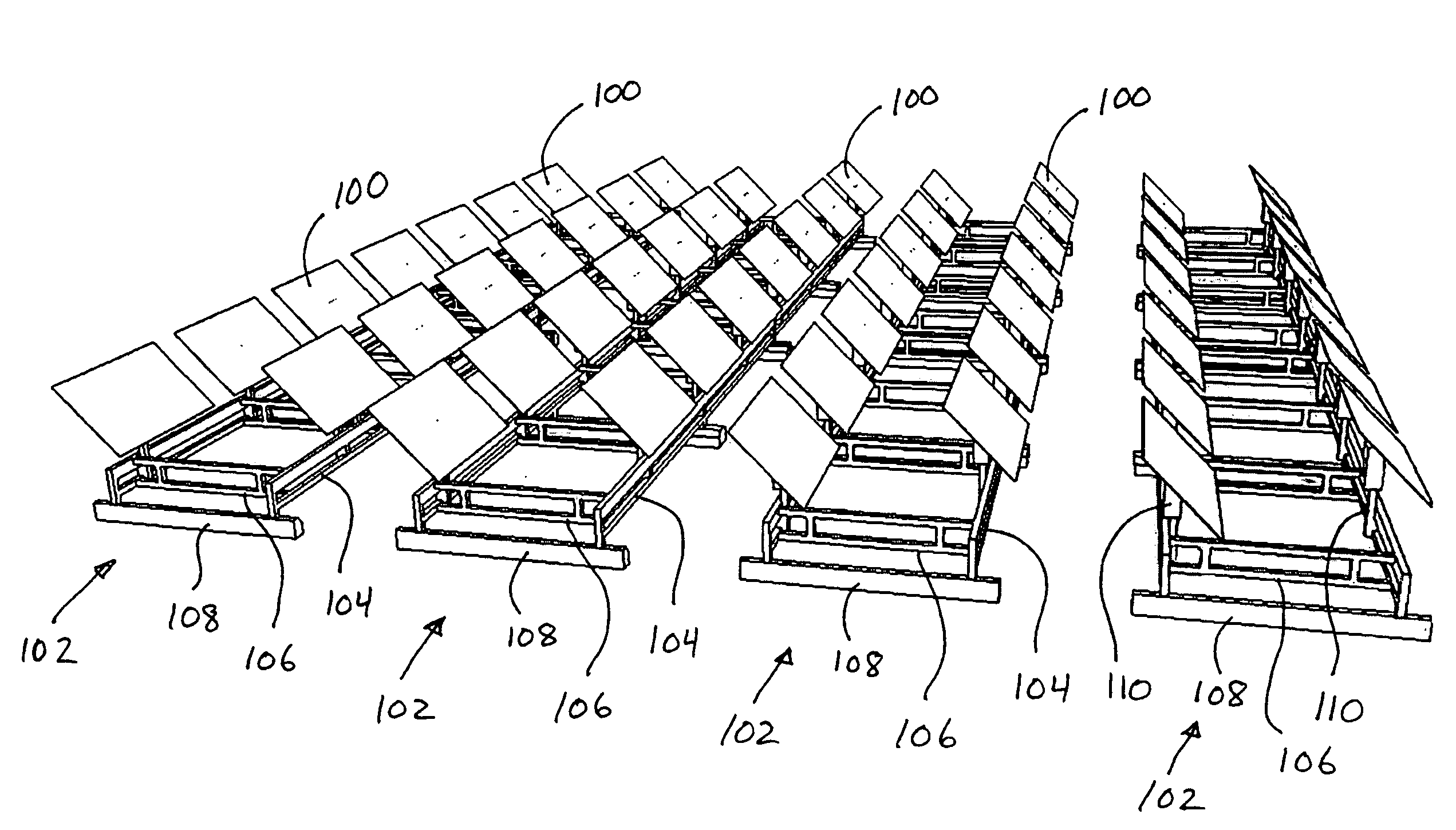
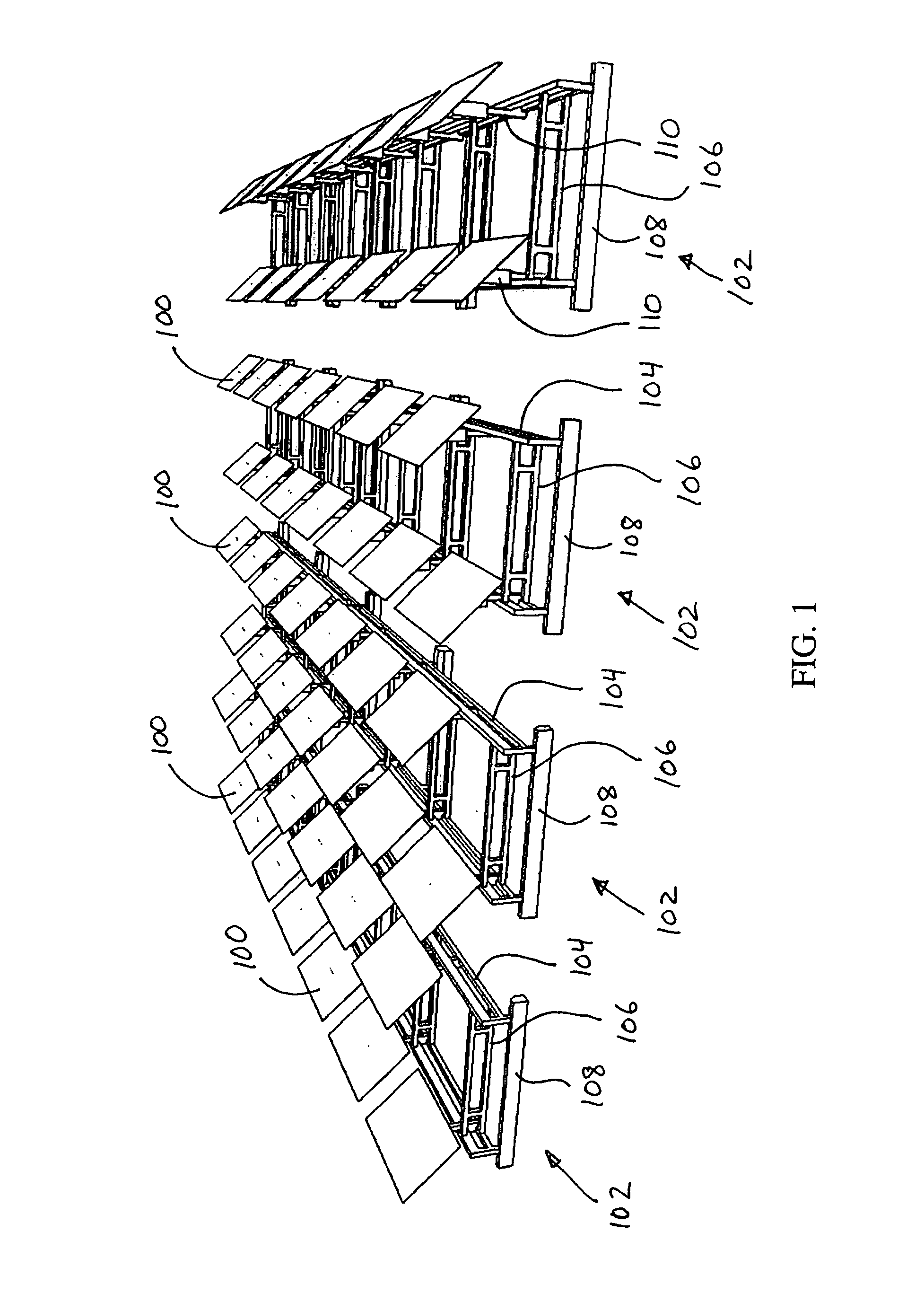
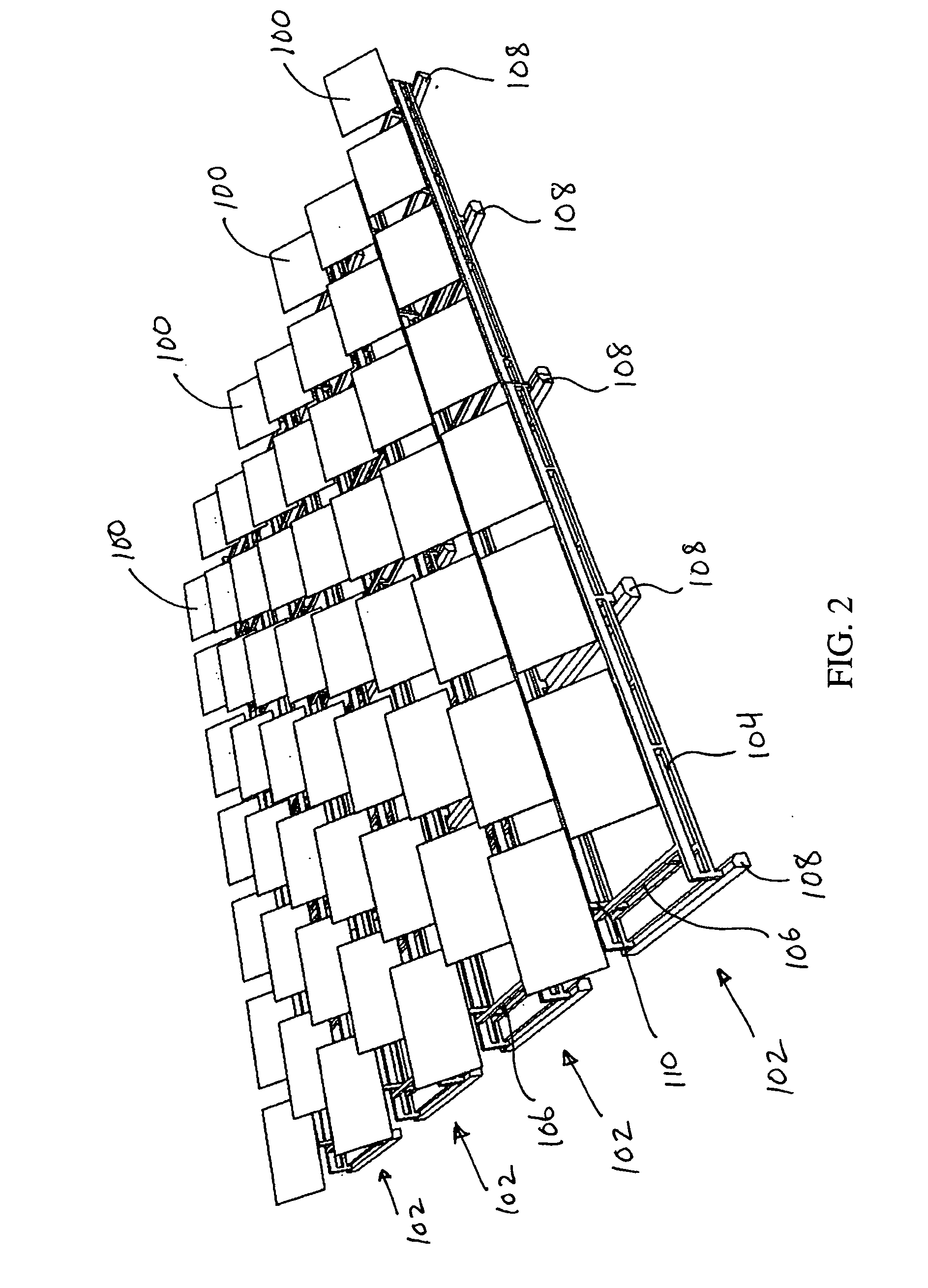
[0064]Referring to FIGS. 1-3, a solar collector system having a plurality of SBH systems is shown. Each SBH system includes a plurality of mirrors 100 moveably mounted on a frame 102. Each frame 102 includes a plurality of side members 104 and a plurality of cross members 106 extending between and connecting the side members 104. In this embodiment, the cross members 106 are generally perpendicular to the side members 104. The cross members 106 provide structural support to the side members 104 and maintain the side members 104 in a fixed position relative to each other. Each SBH system is supported on the ground by one or more ballasts 108, which can be a heavy object so as to maintain the SBH system in a fixed position on the ground with little or no ground penetration. The ballasts 108 can be constructed from any material such as concrete and can have any shape. For example, as shown in FIGS. 1-3, the ballasts 108 can be similar in shape to concrete car stops used in parking fac...

second embodiment

[0067]Referring to FIGS. 6-18, an SBH system and various components thereof according to the disclosure are shown. The SBH system includes a plurality of mirrors 200 moveably mounted on a frame 202. Each frame 202 includes a plurality of side members 204 and a plurality of cross members 206 extending between and connecting the side members 204 to provide rigidity to the frame 202. In this embodiment, the cross members 206 are pivotally connected together in an “accordion style” that allows collapsing of the cross members 206 to a shipping configuration and deployment thereof onsite for assembly. Each SBH system is supported on the ground by one or more ballasts 208. Each ballast 208 can be a heavy object so as to maintain the SBH system in a fixed position on the ground with little or no ground penetration. The ballasts 208 are shown to be similar in shape to concrete car stops. The ballasts 208 secure the SBH system on the ground while providing a surface area large enough to distr...

third embodiment

[0078]The SBH system of the third embodiment includes a plurality of mirrors (not shown) moveably mounted on a frame 302. Each frame 302 includes a plurality of side members 304 and a plurality of cross members 306 connecting the side members 304. The cross members 306 are pivotally connected together in an “accordion style.” Additionally, the pivotal accordion arrangement of the cross members 306 allows collapsing of the cross members 306 to a shipping configuration and deployment thereof onsite for assembly. Each SBH system is supported on the ground by one or more ballasts 308 (a single ballast 308 is shown in FIG. 19), which are configured to maintain the SBH system in a fixed position on the ground with little or no ground penetration. As described below, the ballasts 308 can be formed on site by pouring concrete in ballast bags 350 coupled to the frame 302. Each mirror is mounted to a corresponding frame 302 with a stantion 310 vertically extending from the frame 302. The stan...


PUM


Abstract

A solar collector system includes a plurality of frames. Each frame includes at least a pair of spaced apart side members, a plurality of cross members connected to the side members, the cross members pivotally moveable from a shipping configuration to a deployed configuration wherein in the deployed configuration, each cross member is positioned relative to an adjacent cross member with a predetermined angle, and a plurality of stantions extending from the frames. The solar collector system further includes a plurality of heliostats, each heliostat mounted to one of the stantions, and a plurality of ballasts coupled to the frames, each ballast having a lower surface contacting the ground without substantially penetrating the ground to maintain a position of the frames on the ground.

Description

CROSS-REFERENCE TO RELATED APPLICATIONS[0001]The present application claims the benefit of U.S. Provisional Patent Application Ser. No. 60 / 933,816, filed Jun. 8, 2007, the entire disclosure of which is incorporated herein by reference, and further claims the benefit of U.S. Provisional Patent Application Ser. No. 61 / 069,806, filed Mar. 18, 2008, the entire disclosure of which is incorporated herein by reference.BACKGROUND[0002]Power tower solar collector systems typically employ a large number of heliostat-supported mirrors that reflect sunlight to a tower, by which electricity is directly or indirectly generated. Said heliostats are usually arranged on the ground along concentric arcs at different positions around the tower. To avoid blocking from arc to arc, the distance between these is an increasing function of radius. To track the position of the sun throughout the day, each heliostat moves to a configuration which reflects the sun toward the tower. Each heliostat is anchored t...

Claims


Application Information

Patent Timeline
IPC IPC(8): F24J2/36F24S50/20
CPCF24J2/5239F24J2/5245F24J2/525F24J2/526F24J2/5264F24J2/542F24J2002/5486F24J2002/5277F24J2002/5292Y02E10/47F24J2/523F24J2/461F24J2/5233F24J2002/4669F24S25/10F24S25/13F24S25/16F24S25/61F24S25/617F24S25/65F24S25/70F24S30/452F24S40/20F24S2025/012F24S2025/02F24S2025/6006F24S2030/16
Inventor LUCONI, GREGGGREGORY, CHRISCOLEMAN, BRIANGREANEY, ALANBLAIR, JASON
Owner SEPCOIII ELECTRIC POWER CONSTR CO LTD
Why Eureka
Try Eureka