Display Device

Inactive Publication Date: 2009-01-08
PANASONIC CORP
View PDF17 Cites 51 Cited by
  • Summary
  • Abstract
  • Description
  • Claims
  • Application Information

AI Technical Summary

Benefits of technology

[0018]In the present invention, the rear case includes a first air-hole area and a second air-hole area, and no air-hole is provided in the shielded area surrounded by the first air-hole area, the second air-hole area and external common tangents thereof. With this structure, smooth air flow within the rear space can be secured using the function of the exhaust fans, and accordingly radiation effect can be improved. Therefore, at least in the shielded area, even if the temperature of the air rises, it is possible to exhaust the air to the outside using the function of the exhaust fan, while the air flow from the second air-hole area to the first air-hole area is not obstructed. Since a circuit substrate on which a drive circuit for the display

Problems solved by technology

However, with the structure stated in the Patent Document 1, the flow of air from the bottom to the top of the rear space might be obstructed due to the structure having many passages for the intake air.
As a result, the heat radiation efficiency of the rear space can not be secured, and parts generating heat at high temperature can not be cooled enough.
As a result, the function of the exhaust fan can not be fu

Method used


Image

  • Display Device
  • Display Device
  • Display Device

Examples


first embodiment

Overall Structure

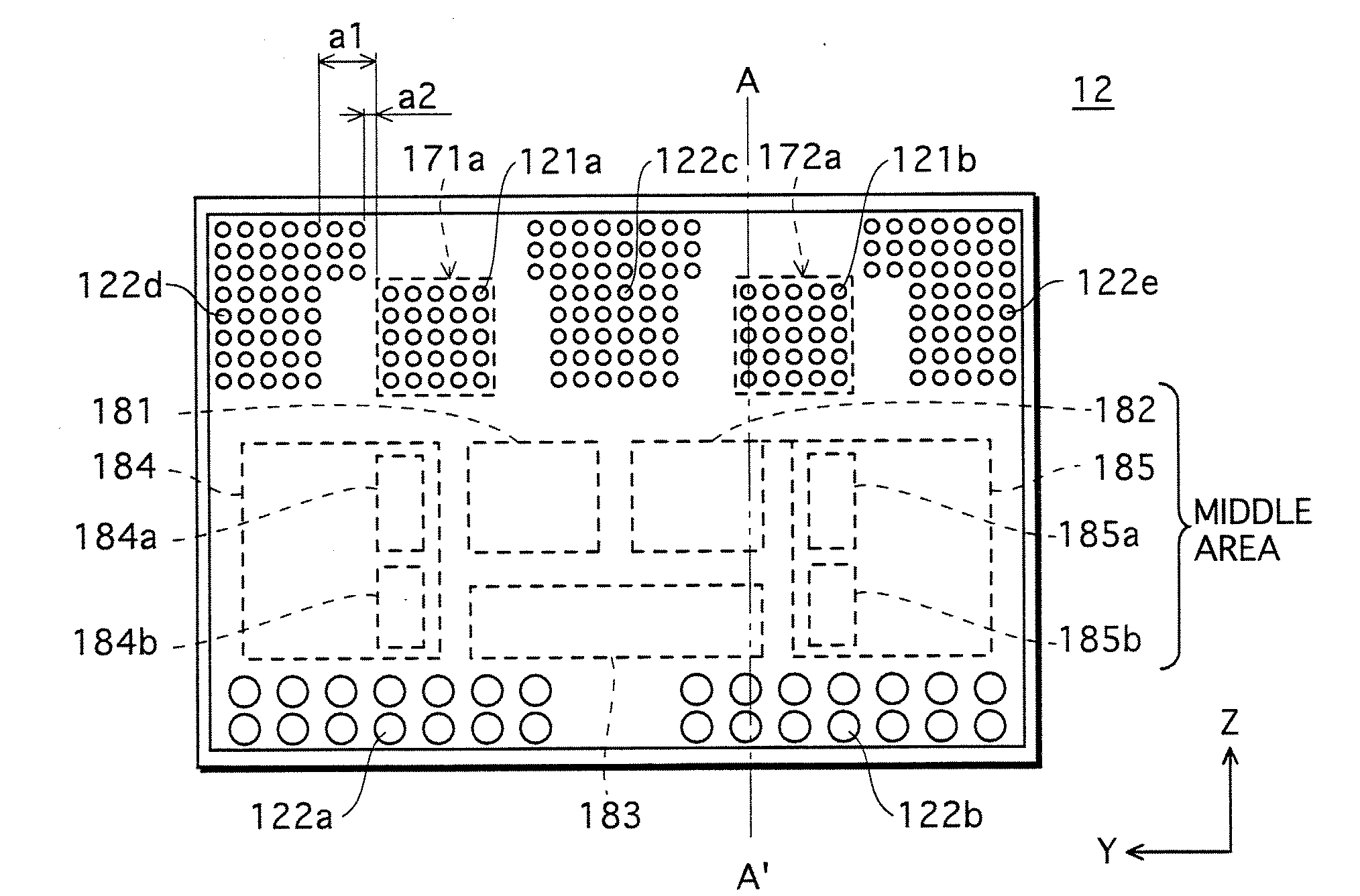
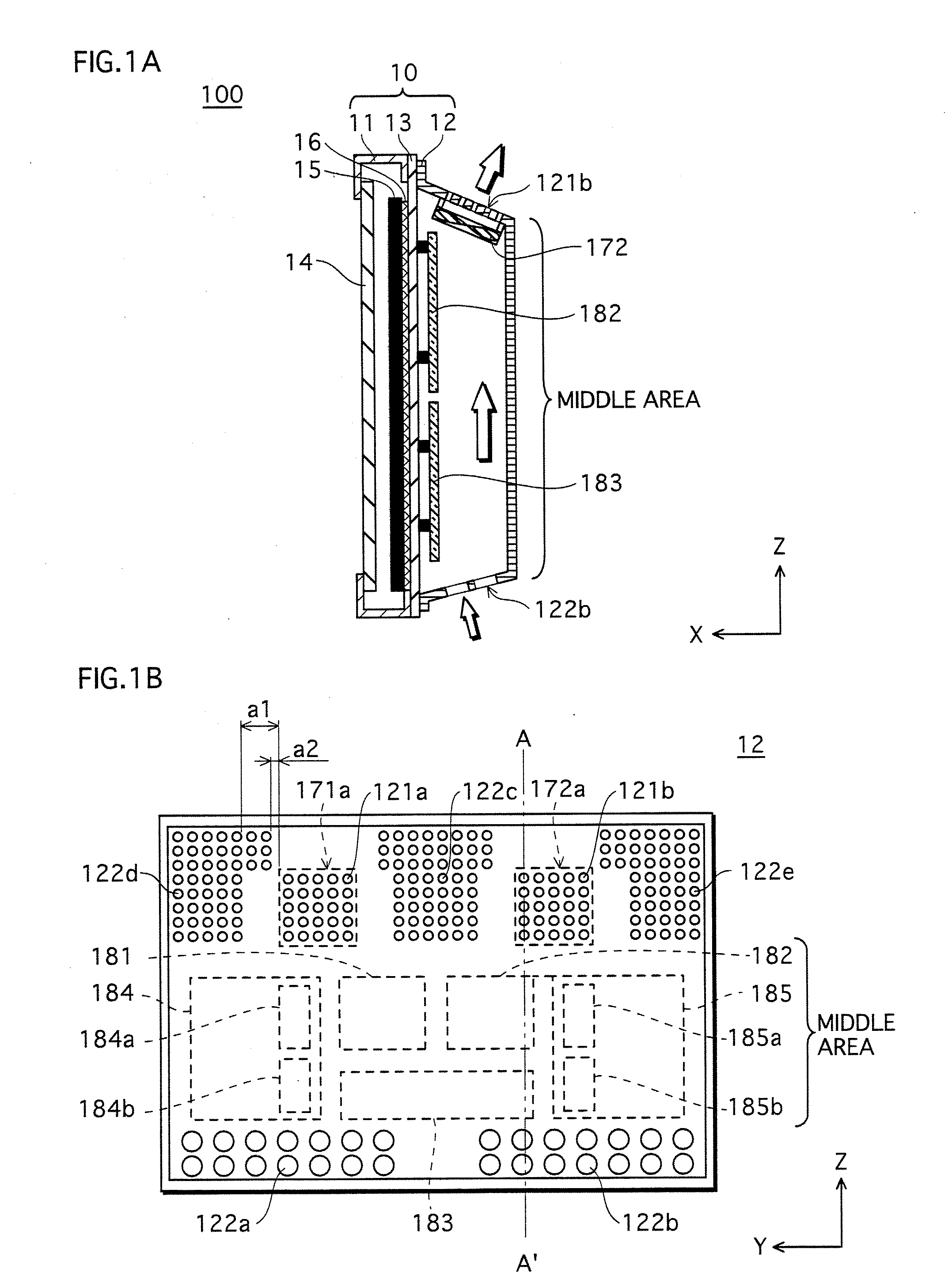
[0056]FIG. 1A is a lateral cross-section view of a PDP apparatus 100, and FIG. 1B is a plan view schematically showing the rear side of the PDP apparatus 100. The cross section shown in FIG. 1 corresponds to the cross section cut along A-A′ shown in FIG. 1B.

[0057]As FIG. 1A shows, in the PDP apparatus 100, a case 10 is structured with a front case 11 made of organic resin and a rear case 12 made of thermally-conductive metal such as aluminum (Al), between which a frame chassis 13 of aluminum die-cast intervenes.

[0058]The front case 11 has an opening on the front side (the side indicated by an arrow X) and a filter 14 is placed to cover the opening. This filter 14 prevents electromagnetic rays and infrared rays, and improves the contrast. Within the front case 11, a thermally-conductive sheet 16 and a PDP 15 (e.g. 42-inch type) are disposed on the frame chassis 13 in this order. The frame chassis 13 radiates the heat generated by the gas discharge of the PDP 15 to in...

modification example 1

[0089]The following describes a modification example 1 of the present invention, with reference to FIG. 8. FIG. 8 is a plan view schematically showing a PDP apparatus viewed from the rear side. This modification example is the same as the first embodiment above, except for the natural exhaust hole groups. Accordingly, the description of the same parts is omitted.

[0090]As FIG. 8 shows, natural exhaust hole groups 222c, 222d and 222e are provided in a rear case 22. The natural exhaust hole group 222c is provided in substantially the middle of the natural exhaust hole groups in the horizontal direction (Y direction). Fan areas 271d and 272a are each provided at a certain distance from the exhaust hole group 222c. The natural exhaust hole groups 222d and 222e are respectively provided in the vicinities of the margins of the rear case 22. The exhaust hole groups 222d and 222e are respectively positioned at a certain distance from the fan areas 271a and 272a. All the certain distance ment...

modification example 2

[0092]Another modification example is explained next with reference to FIG. 9. FIG. 9 is a plan view schematically showing a PDP apparatus viewed from the rear side. This modification example is also the same as the first embodiment above, except for the natural exhaust hole groups. Accordingly, the description of the same parts is omitted.

[0093]As FIG. 9 shows, natural exhaust hole groups 322c, 322d and 322e are provided in a rear case 32, and they are positioned in a part that is upper than fan areas 371a and 372a (positioned on the side indicated by the arrow Z) so as to be at a distance a2 in the horizontal direction (Y direction) from the fan areas 371a and 372a respectively. As described above, a2=0.17b is satisfied, where b (m3 / min.) is an exhaust amount of the fan.

[0094]The structure of this modification example also can achieve effective radiation. The partition plate may be used in the same manner to certainly partition the rear space.


PUM


Abstract

The present invention provides a display apparatus that can achieve high durability by making the most of the function of the exhaust fans to effectively suppress the rise of the temperature. The display apparatus comprises a display panel for displaying images, a rear case covering a rear side of the display panel, and an exhaust fan disposed within the rear case, wherein the rear case includes a first air-hole area and a second air-hole area each provided with a plurality of air holes, the first air-hole area is located at a higher level than the second air-hole area with respect to a vertical direction with a spacing therebetween, and at least partially faces the exhaust fan, and an area surrounded by the first air-hole area, the second air-hole area and external common tangents thereof is a shielded area in which no air hole is provided.

Description

TECHNICAL FIELD[0001]The present invention relates to a rear case of a display apparatus such as a plasma display apparatus, and particularly relates to a technique to efficiently radiate heat generated in the apparatus to outside the apparatus.BACKGROUND ART[0002]In a plasma display panel apparatus (Hereinafter called “a PDP apparatus”), image display is performed using plasma discharge. Accordingly, in general, a panel case, many electronic elements and the likes generate heat to drive the panel. If this heat remains inside the apparatus, the panel and the electronic elements are exposed to an unfavorable temperature environment. As a result, the life and the performance of the apparatus can be degraded. In view of this problem, some measures are taken, e.g., suppressing the heat by various methods and providing many air holes in the rear case. Especially, since the heat generation amount has been increasing recently with the realization of a function of display apparatuses for di...

Claims


Application Information

Patent Timeline
IPC IPC(8): H01J61/52
CPCH05K7/20972H05K7/20009Y10S345/905
Inventor YANAGAWA, HIROTOTAKEZAWA, HIROAKI
Owner PANASONIC CORP
Why Eureka
Try Eureka