
Lighting control device of lighting device for vehicle

Active Publication Date: 2009-01-08
KOITO MFG CO LTD
View PDF6 Cites 48 Cited by
  • Summary
  • Abstract
  • Description
  • Claims
  • Application Information

AI Technical Summary

Benefits of technology

[0018]When the ON / OFF operations of each of the semiconductor light sources are to be individually controlled based on the communication information transferred from the outside, the specified current value (a sum total of the currents supplied to the semiconductor light sources serving as the lighting targets) is calculated based on the ON / OFF operations of the semiconductor light source, and furthermore, the current output from the switching regulator is detected and the current value thus detected is compared with the specified current value. If the detected current value is greater than the specified current value, it is decided that a current flows without the series regulator and the grounding is generated. Therefore, it is possible to detect, with high precision, that the grounding is generated on the cathode side of any of the semiconductor light sources irrespective of the semiconductor light source serving as the lighting target or a non-lighting target. It is possible to protect the semiconductor light source from a grounding accident by stopping the operation of the switching regulator when detecting the grounding.
[0022]The stop period for which the series regulator is stopped is provided immediately after the switching regulator is started, and the specified current value for the stop period is set to be zero and the detected current value is compared with the specified current value of zero for the stop period. If the detected current value is greater than the specified current value of zero, it is decided that the series regulator is set into a non-operating state and a current flows from the switching regulator to any of the semiconductor light sources, and grounding is generated though all of the semiconductor light sources serve as non-lighting targets. Even if the current flowing with the grounding is a microcurrent, therefore, it is possible to detect, with high precision, that the grounding is generated on the cathode side of any of the semiconductor light sources. It is possible to protect the semiconductor light source from a grounding accident before turning ON the semiconductor light source by stopping the operation of the switching regulator when detecting the grounding.
[0023]As is apparent from the description, according to the lighting control device of a lighting device for a vehicle in accordance with the first aspect of one or more embodiments of the invention, it is possible to detect, with high precision, that the grounding is generated on the cathode side of the semiconductor light source and to protect the semiconductor light source from a grounding accident.
[0025]According to the third aspect of one or more embodiments of the invention, even if the current flowing with the grounding is a microcurrent, it is possible to detect, with high precision, that the grounding is generated on the cathode side of any of the semiconductor light sources and to protect the semiconductor light source from a grounding accident before turning ON the semiconductor light source.

Problems solved by technology

However, individual ON / OFF operations of each of the semiconductor light sources (LEDs) is not taken into consideration.
In the case in which only one LED (the semiconductor light source) serves as the lighting target, the LED cannot be protected by generation of grounding with a structure in which the operation of the switching regulator is stopped when an abnormality of at least two LEDs (semiconductor light sources) is detected.

Method used


Image

  • Lighting control device of lighting device for vehicle
  • Lighting control device of lighting device for vehicle
  • Lighting control device of lighting device for vehicle

Examples


Embodiment Construction

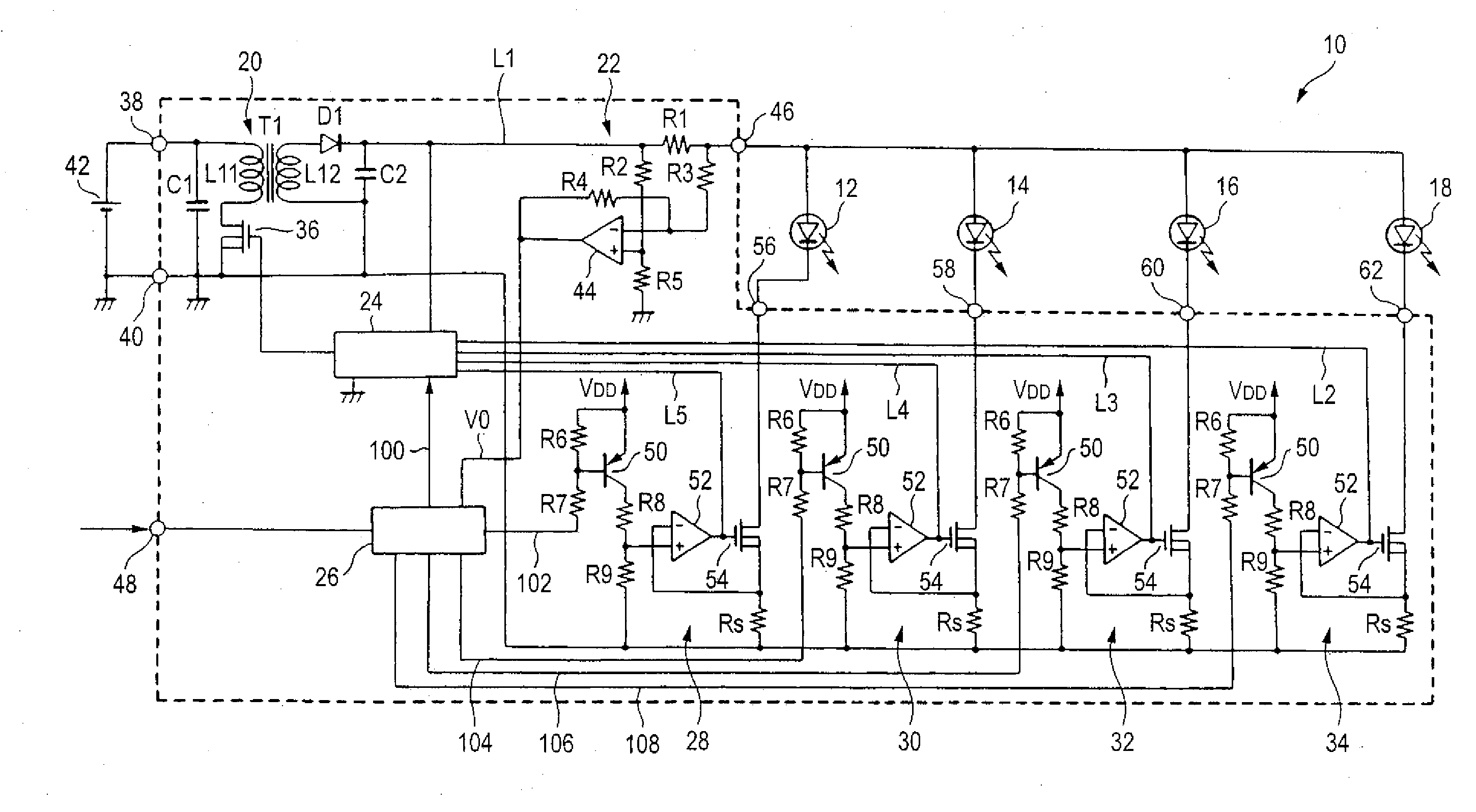
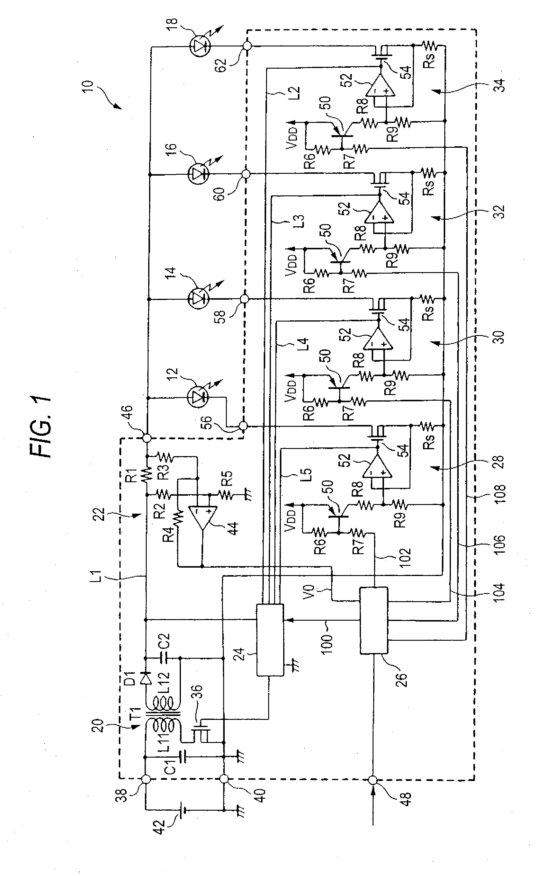
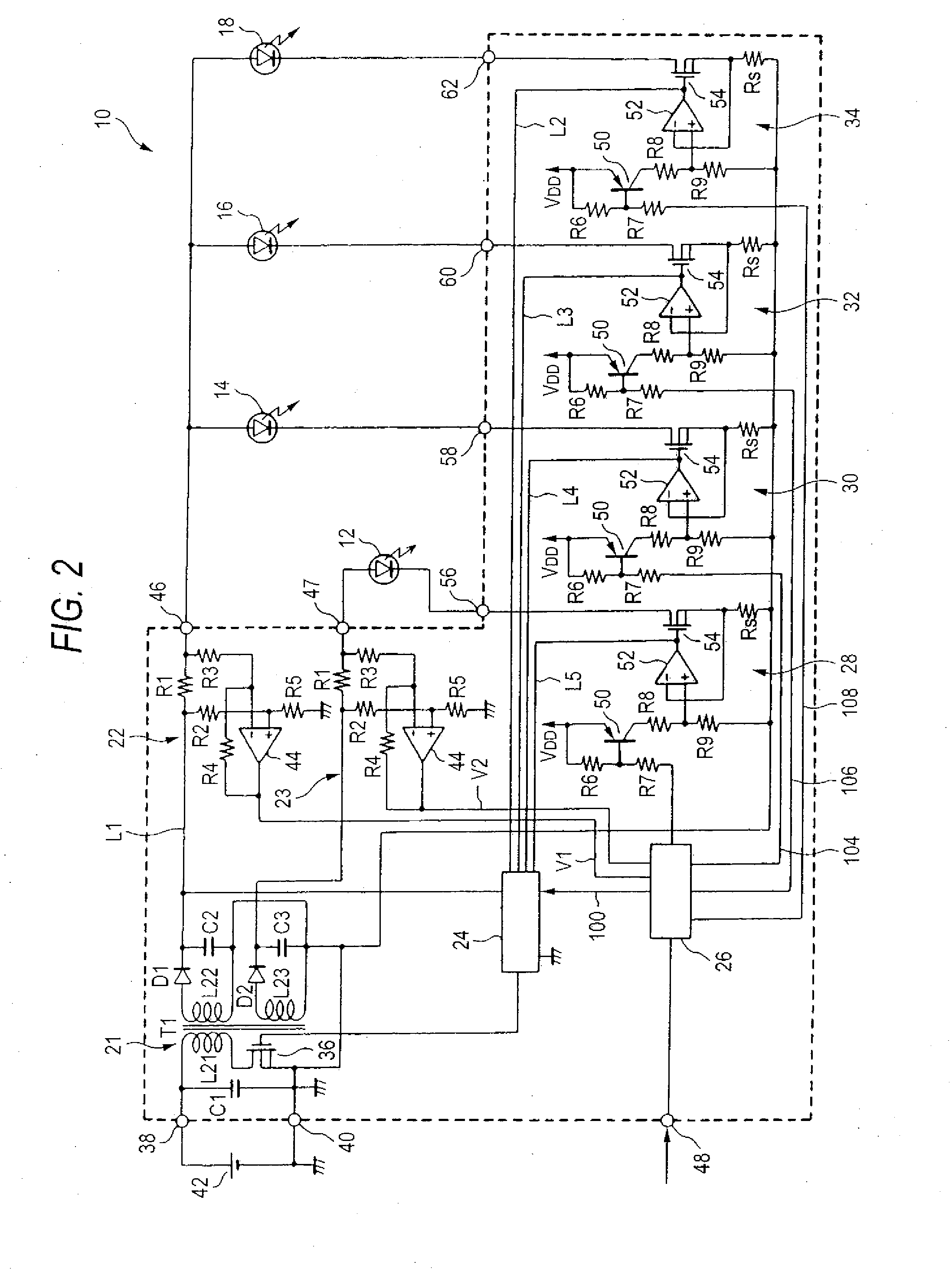
[0030]Embodiments of the invention will be described below with reference to the drawings. FIG. 1 is a block diagram showing a structure of a lighting control device of a lighting device for a vehicle according to a first example of one or more embodiments of the invention, FIG. 2 is a block diagram showing a structure of a lighting control device of a lighting device for a vehicle according to a second example of one or more embodiments of the invention, and FIG. 3 is a chart for explaining an operation according to a third example of one or more embodiments of the invention, (a) being a time chart showing an operating state of each portion in a normal state and (b) being a time chart showing an operating state of each portion in grounding.

[0031]In FIG. 1, alighting control device 10 of a lighting device (a light emitting device) for a vehicle comprises a switching regulator 20 for setting, as loads, LEDS 12, 14, 16 and 18 to be four types of light sources, a current detecting circ...


PUM


Abstract

In a process in which a control signal having a low level is output from an ON / OFF control circuit to series regulators connected to LEDs serving as lighting targets to turn ON the LEDs in accordance with digital communication information, the ON / OFF control circuit calculates a specified current value to be supplied to the LEDs serving as the lighting targets and compares the specified current value with a detected current value which is detected by a current detecting circuit, and outputs a stop signal to a control circuit on the assumption that a current flows without the series regulators with grounding generated on a cathode side of any of LEDs when the detected current value is greater than the specified current value. When the control circuit turns OFF an NMOS transistor in response to the stop signal, an operation of a switching regulator is stopped.

Description

BACKGROUND OF INVENTION[0001]1. Field of the Invention[0002]The present invention relates to a lighting control device of a lighting device for a vehicle and, more particularly, to a lighting control device of a lighting device for a vehicle which controls a lighting operation of a semiconductor light source formed by a semiconductor light emitting device.[0003]2. Background Art[0004]Conventionally, there has been known a lighting device for a vehicle which uses, as a light source, a semiconductor light emitting device such as an LED (Light Emitting Diode), and a lighting control device for controlling a lighting operation of the LED is mounted on the lighting device for a vehicle of this type.[0005]There has been known a lighting control device comprising a series regulator connected in series to an LED and serving to carry out a control for causing a specified current to flow to the LED and a switching regulator for controlling an output voltage applied to the LED to be a maximum ...

Claims


Application Information

Patent Timeline
IPC IPC(8): H05B37/02H05B41/36
CPCH05B33/0815H05B33/0887H05B33/0827H05B45/50H05B45/46H05B45/385
Inventor ITO, MASAYASUNAMBA, TAKANORI
Owner KOITO MFG CO LTD
Features
  • Generate Ideas
  • Intellectual Property
  • Life Sciences
  • Materials
  • Tech Scout
  • Unparalleled Data Quality
  • Higher Quality Content
  • 60% Fewer Hallucinations
Learn More