Anti-Theft Location Check Device

Active Publication Date: 2009-01-08
ARBOPROFIT
17 Cites 21 Cited by

AI-Extracted Technical Summary

Problems solved by technology

By disabling only a part of the functionality of an electronics apparatus, it is immediately clear to a possible buyer that the apparatus has been stolen, as it doesn't function properly, however, fo...

Method used

[0024]The processing means 1 provide an interrupt signal to an electronics apparatus 5, e.g. PC or DVD-player or the like, in order to disable at least a part of a functionality of the electronics apparatus 5, if the retrieved actual location does not match the retrieved permissible location. For example, in case of a DVD-player, only the receiver of the remote control that is mounted in the DVD-player could be disabled, limiting the functionality of the DVD-player to the functionality associated with the control buttons on the front plate of the DVD-player. In an alternative embodiment, e.g. the disc tray of the DVD-player is disabled if the actual location differs from the permissible location. A screen or display of a television could be disabled in a further exemplary embodiment. Also, bias voltage of one or more electrical amplifiers in the electronics apparatus could be reduced to generate an interference signal that prevents the electronics apparatus from operating according to specifications, such as e.g. minimum SNR (Signal-to-Noise Ratio) in case of a CD-player. Furthermo...

Benefits of technology

[0006]The present invention aims to provide an anti-theft device, which is particularly suited to prevent theft of electrical apparatus, more specifically consumer ele...

Abstract

An anti-theft device for an electronics apparatus, including (a) locating means for determining an actual location, (b) storage means for storing a permissible location, and (c) processing means connected to the locating means and storage means. The processing means is configured to retrieve the actual location from the locating means, and to compare the actual location against the permissible location. The processing means is further configured to disable at least part of the functionality of the electronics apparatus if the actual location is more than a predetermined distance from the permissible location. The processing means is further configured to enter the anti-theft device in a standby mode, wherein the electronics apparatus is never disabled by the anti-theft device, and the standby mode may be entered for a predetermined time period.

Application Domain

Technology Topic

Image

  • Anti-Theft Location Check Device
  • Anti-Theft Location Check Device
  • Anti-Theft Location Check Device

Examples

  • Experimental program(1)

Example

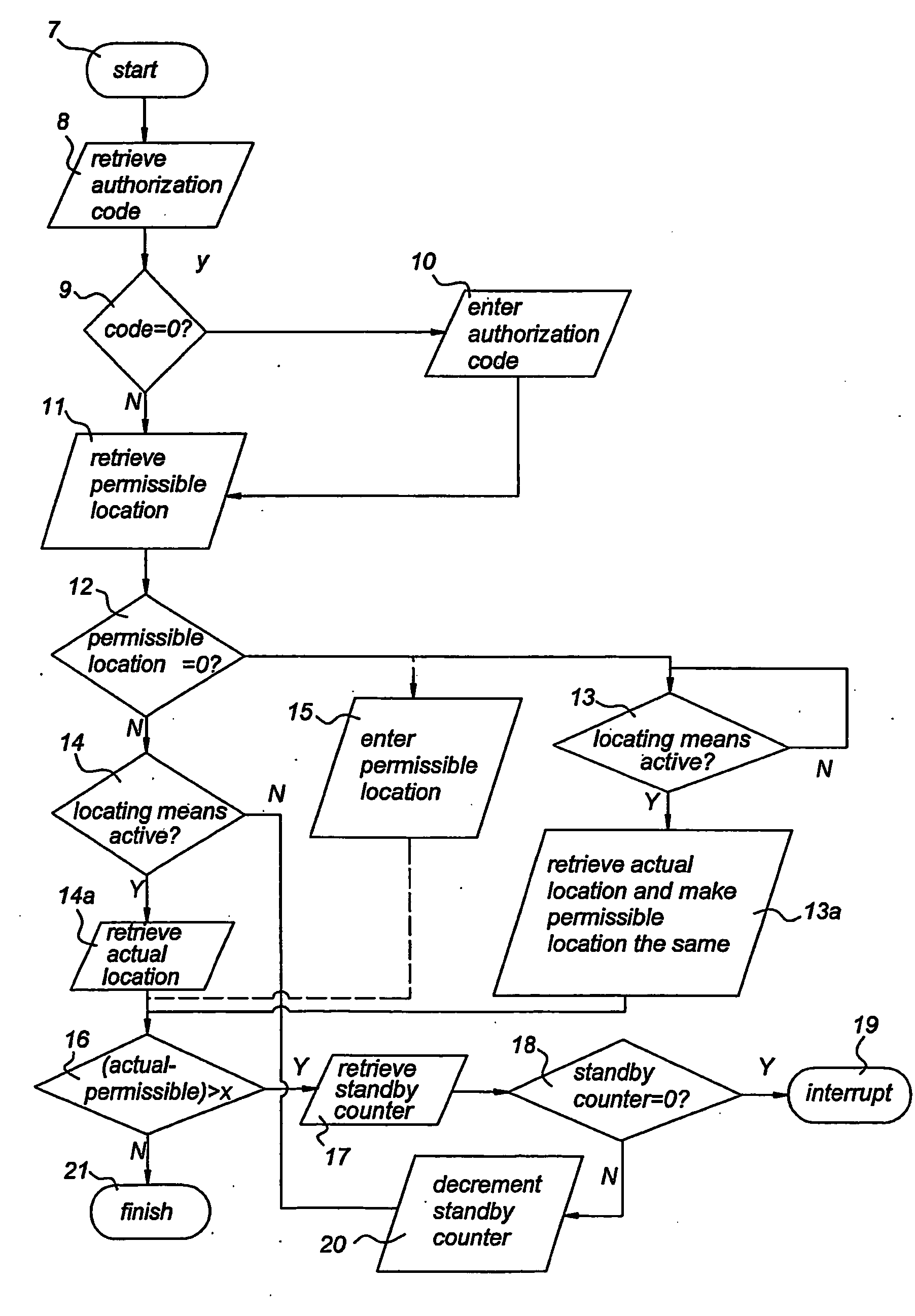
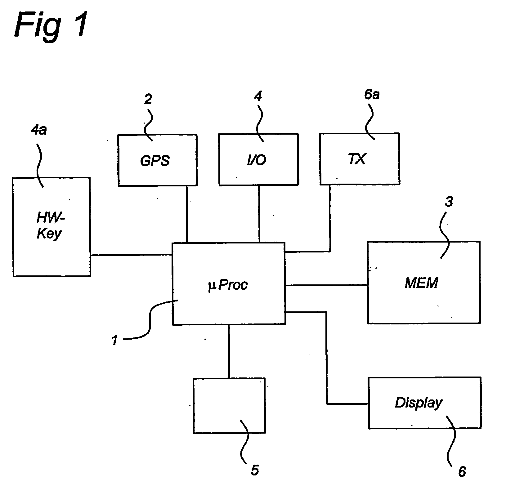
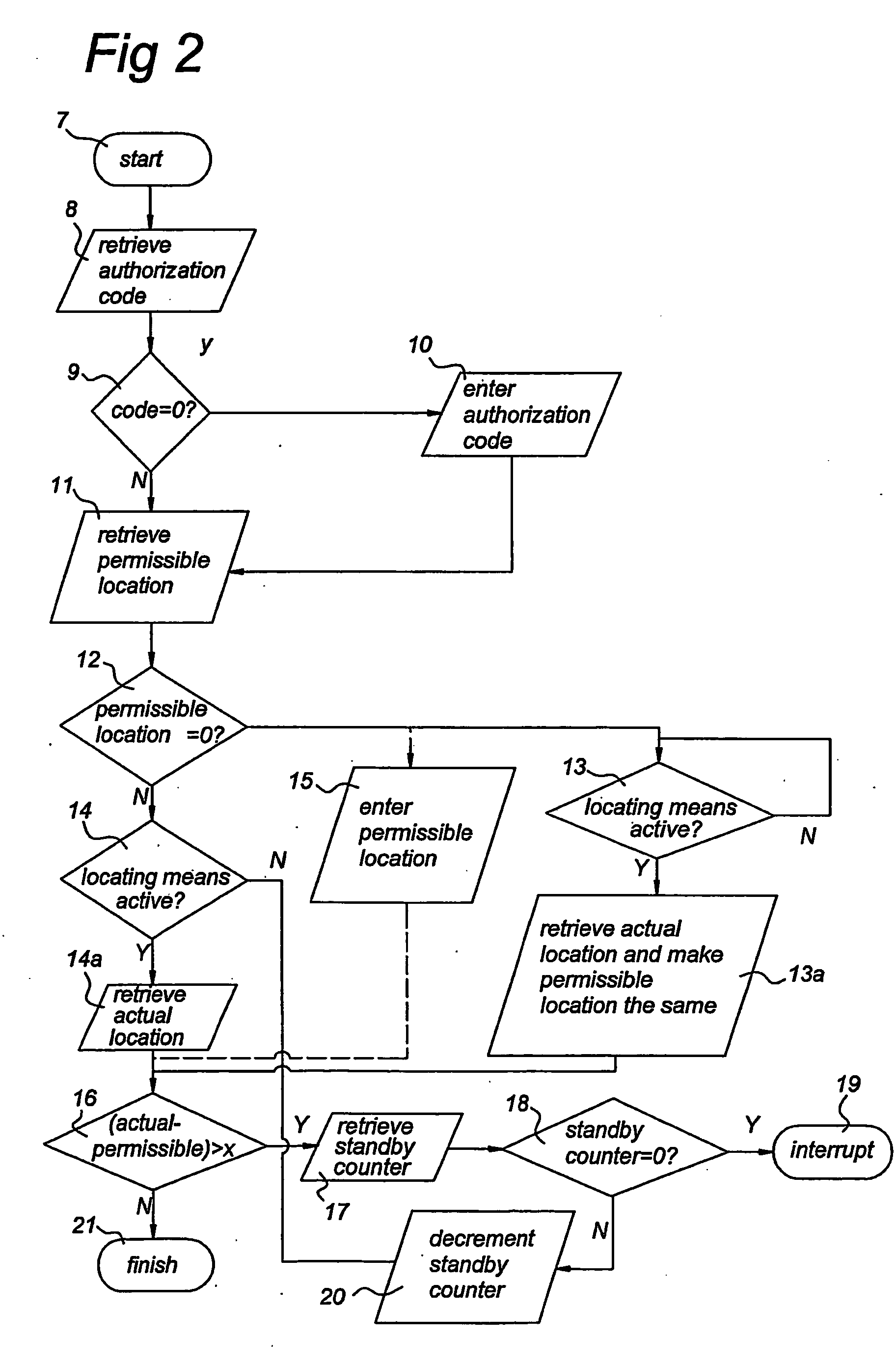
[0023]FIG. 1 schematically depicts a diagram of the theft control device or anti-theft device according to an embodiment of the present invention. Processing means 1, connected to locating means 2 and storage means 3, retrieve an actual location from the locating means 2 and a permissible location from the storage means 3.
[0024]The processing means 1 provide an interrupt signal to an electronics apparatus 5, e.g. PC or DVD-player or the like, in order to disable at least a part of a functionality of the electronics apparatus 5, if the retrieved actual location does not match the retrieved permissible location. For example, in case of a DVD-player, only the receiver of the remote control that is mounted in the DVD-player could be disabled, limiting the functionality of the DVD-player to the functionality associated with the control buttons on the front plate of the DVD-player. In an alternative embodiment, e.g. the disc tray of the DVD-player is disabled if the actual location differs from the permissible location. A screen or display of a television could be disabled in a further exemplary embodiment. Also, bias voltage of one or more electrical amplifiers in the electronics apparatus could be reduced to generate an interference signal that prevents the electronics apparatus from operating according to specifications, such as e.g. minimum SNR (Signal-to-Noise Ratio) in case of a CD-player. Furthermore, a portion of the software embedded in a storage means of the electronics apparatus could be disabled in a further embodiment.
[0025]In a further advantageous embodiment of the present invention, upon activation of the theft control device, the processing means 1 retrieve the actual location from the locating means 2 and record the actual location in the memory location for the permissible location in the storage means 3. This is an attractive solution since the permissible location is set up without a need for knowledge on defining the permissible location by the user.
[0026]Furthermore, user interface 4 is connected to the processing means 1 and is arranged for providing coordinates of one or more permissible locations to the processing means 1 for storage in the local storage means 3. The coordinates of the permissible locations could e.g. be a postal zip code and a home number, a pair of longitudinal and latitudinal coordinates or a set of GPS coordinates. It is important to note that such an arrangement may require a conversion of the coordinates of the permissible location to the coordinate-system of the actual location in order to be able to compare the permissible and the actual location.
[0027]The user interface 4 is further arranged for activating a standby mode, which overrules the interruption of the at least a part of the functionality of the electronics apparatus 5 by the theft control device in case of a discrepancy between the actual and permissible location. This feature allows reparation of the electronics apparatus 5 at a location different than the permissible location(s) or use of the theft control device in mobile electronics apparatuses 5. The standby mode can only be activated at a permissible location in a specific embodiment. In a further embodiment, the standby mode could be enabled by physically connecting a hardware key 4a, e.g. a USB (Universal Serial Bus) hardware key, to the processing means 1 while the electronics apparatus 5 is located at the permissible location.
[0028]The processing means 1 are further connected to a display 6 being arranged to show the permissible location that is stored in the storage means 3. In a further embodiment, the user interface 4 is arranged to provide a zip code of the permissible location to the processing means 1 for storage in the storage means 3 and the display 6 is further arranged to show the zip code that is stored in the storage means 3.
[0029]The processing means 1 may e.g. comprise digital processing circuits, analogue processing circuits or a combination of both, and may be operating under software instructions. The storage means 3 may comprise any type of data storage, such as, but not limited to, RAM, PROM, etc. The locating means 2 may comprise components which are arranged to perform receiver type of functions, such as RF signal processing, e.g. in the form of a GPS receiver and corresponding antenna. Furthermore, the processing means 1, the storage means 3, or both, may be partially or completely integrated in a monolithically grown electronic circuit, in a further embodiment, rendering any modification of the theft control device, in order to circumvent it, practically impossible. Also, the processing means 1 and the storage means 3, or both, may be monolithically integrated with a processing means, e.g. a CPU, of the electronics apparats in order to further render any modification of the anti-theft device difficult.
[0030]In a further embodiment of the present invention, the actual location is retrieved from a GPS (Global Positioning System) and the coordinates of the permissible location, e.g. the combination of a postal zip code and a home number, is converted into a set of GPS coordinates and stored in the local storage means 3. By doing this, the determined actual location can be easily compared to the permissible location without conversion of the format which minimizes the required processing power compared to the case where the GPS coordinates have to be converted to a postal zip code and a home number at every check of the actual location.
[0031]The standby mode could, in a further embodiment, be enabled during a user-specified amount of operating time of the processing means 1, e.g. a total number of clock cycles. This may for example be used in case of a repair of the electronics apparatus 5. In an alternative embodiment, the standby mode could be enabled for a predetermined time period specified e.g. by a start time and a completion time. The actual time could, e.g., be retrieved from the locating means 2 in case of a GPS, instead of from a local clock, in order to prevent extension of the absolute duration of the standby time period by changing the time of the local clock. This embodiment is particularly suited for use of an electronic apparatus 5 outside one's house. The electronics apparatus 5 will only be (partially) disabled when it is not back in the permissible location (area) after the completion time.
[0032]In a further embodiment, a transmitter means 6a transmits a signal comprising e.g. the actual location provided by the locating means 2 to e.g. a monitoring station if the actual location is outside the permissible location in order to facilitate a repatriation of the electronic apparatus 5 to the permissible location.
[0033]FIG. 2 is an illustration of a process flow diagram of a method for setting up an authorization code and a permissible location in a theft control device in accordance with an exemplary embodiment of the present invention. The method starts at block7 with the start of the theft control device procedure. At function block 8, the theft control device checks the content of the memory location that is reserved for the authorization code. During normal operation, the authorization code is verified before allowing a change of the permissible location, e.g. in case of a relocation of the owner of the apparatus, or enabling of the standby mode to ensure that the user is a rightful owner and not an unlawful user of the electronics apparatus 5. At block 9, the content of the memory location in the storage means 3 that is reserved for the authorization code is retrieved by the processing means 1. If it is equal to zero, an authorization code needs to be entered via the user interface device 4 at block 10.
[0034]A voice recognition means, including e.g. a microphone for converting voice to an electrical signal and an IC (integrated Circuit) specifically designed for electrical voice signal processing, could be used as a user interface 4 to verify the identity of a user who is attempting to change e.g. the permissible location(s) or enable the standby mode. Alternatively, the identity of the user could be verified by connecting a hardware-key 4a to the processing means 1.
[0035]In case the theft control device has been previously set up, the retrieved authorization code is non-zero, and the processing means 1 proceed to the next step at function block 11 and subsequently retrieves the permissible location from the local storage memory 3. Next the processing means 1 test the value of the permissible location in function block 12. In case the permissible location is non-zero, the method moves to function block 14 to check whether the locating means 2 are functional, e.g. in case of a GPS the processing means 1 will check whether the GPS receives a signal. If this is not true, the method will proceed to function block 17 in order to check whether the standby mode is enabled. If it is true, the actual location will be retrieved at function block 14a. If the permissible location retrieved in function block 11 is zero, the processing means 1 test the proper functionality of the locating means 2 in function block 13a. If the locating means 2 are functional, the permissible location is by retrieving the actual location and making the permissible location equal to the actual location in function block 13a. If not, the processing means 1 will loop back to function block 13 until the locating means 2 are functional.
[0036]In a further embodiment of the present invention, as indicated by the dashed lines to block 15, the permissible location could be defined by the postal zip code and home number of the location where the electronics apparatus 5 will be used. In this case, the theft control device will convert the zip code and home number of the permissible location into coordinates in the format that is provided by the locating means 2, e.g. GPS coordinates, and will store the resulting coordinates in the storage means 3 for future reference and comparison with the GPS coordinates provided by the locating means 2. The conversion of the zip code and home number into, e.g., GPS coordinates could be done by means of a lookup table.
[0037]After setting the permissible location equal to the actual location in block 13a or retrieving the actual location in function block 14a in case the permissible location already exists, the processing means 1 test in function block 16 whether the difference between the actual location and the permissible location is smaller than a predetermined value, e.g. 50 m. If this is true, the electronics apparatus 5 is located at the permissible location, and will be fully functional and operate according to specifications of a supplier of the electronics apparatus. The method will then finish at function block 21. If this is false, the processing means 1 will retrieve the standby counter at function block 17 and test whether the standby counter is equal to zero at function block 18. If the standby counter is equal to zero, the standby mode is not enabled and the processing means 1 will interrupt the at least part of a functionality of the electronics apparatus at function block 19. If the standby counter is non-zero, the standby mode is enabled and the processing means 1 will decrement the standby counter in function block 20, for example at every clock cycle of a CPU clock, and the method will loop back to function block 17 until the standby counter is equal to zero. In this method, the standby counter represents the number of clock cycles of the processing means 1 during which the interruption of at least a part of the functionality of the electronics apparatus is overruled and ensures that the electronics apparatus 5 will be fully functional at e.g. a reparation location which is usually outside the permissible location, or, in case of a mobile electronics apparatus, such as e.g. a video camera or a laptop PC (Personal Computer). In a further embodiment, the standby mode could be specified to be enabled until a predetermined moment in time, e.g. the end of a vacation or business trip, instead of in terms of a maximum number of clock cycles (i.e. total operating time of the processing means 1).
[0038]Alternatively, the function block 16 is arranged to check the actual location against the permissible location repeatedly, e.g. at a predetermined frequency, and the flow chart is adapted to loop back to block 14a when the actual location is within a predetermined distance from the permissible location, instead of proceeding to block 21.
[0039]While specific embodiments of the invention have been described above, it will be appreciated that the invention may be practiced otherwise than as described. The description is not intended to limit the scope of the invention, which is defined by the appended claims. E.g. it will be clear to the person skilled in the art that multiple permissible locations may be stored and used in the present invention.

PUM

no PUM

Description & Claims & Application Information

We can also present the details of the Description, Claims and Application information to help users get a comprehensive understanding of the technical details of the patent, such as background art, summary of invention, brief description of drawings, description of embodiments, and other original content. On the other hand, users can also determine the specific scope of protection of the technology through the list of claims; as well as understand the changes in the life cycle of the technology with the presentation of the patent timeline. Login to view more.

Similar technology patents

Classification and recommendation of technical efficacy words

Why Eureka
Try Eureka