Eureka AIR delivers breakthrough ideas for toughest innovation challenges, trusted by R&D personnel around the world.

Liquid crystal display device

a liquid crystal display and display device technology, applied in static indicating devices, cathode-ray tube indicators, instruments, etc., can solve the problems of unnecessarily enlarged liquid crystal panels, increased control circuit costs, and increased costs of liquid crystal panels

Inactive Publication Date: 2009-01-08
FUNAI ELECTRIC CO LTD
View PDF10 Cites 6 Cited by
  • Summary
  • Abstract
  • Description
  • Claims
  • Application Information

AI Technical Summary

Benefits of technology

[0013]By driving a high-resolution liquid crystal display device using low-priced and low-resolution pixel count conversion unit, a low-cost liquid crystal display device is provided.
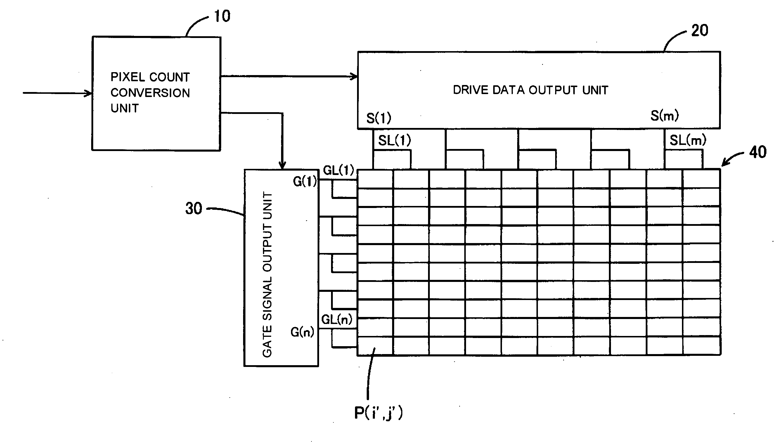
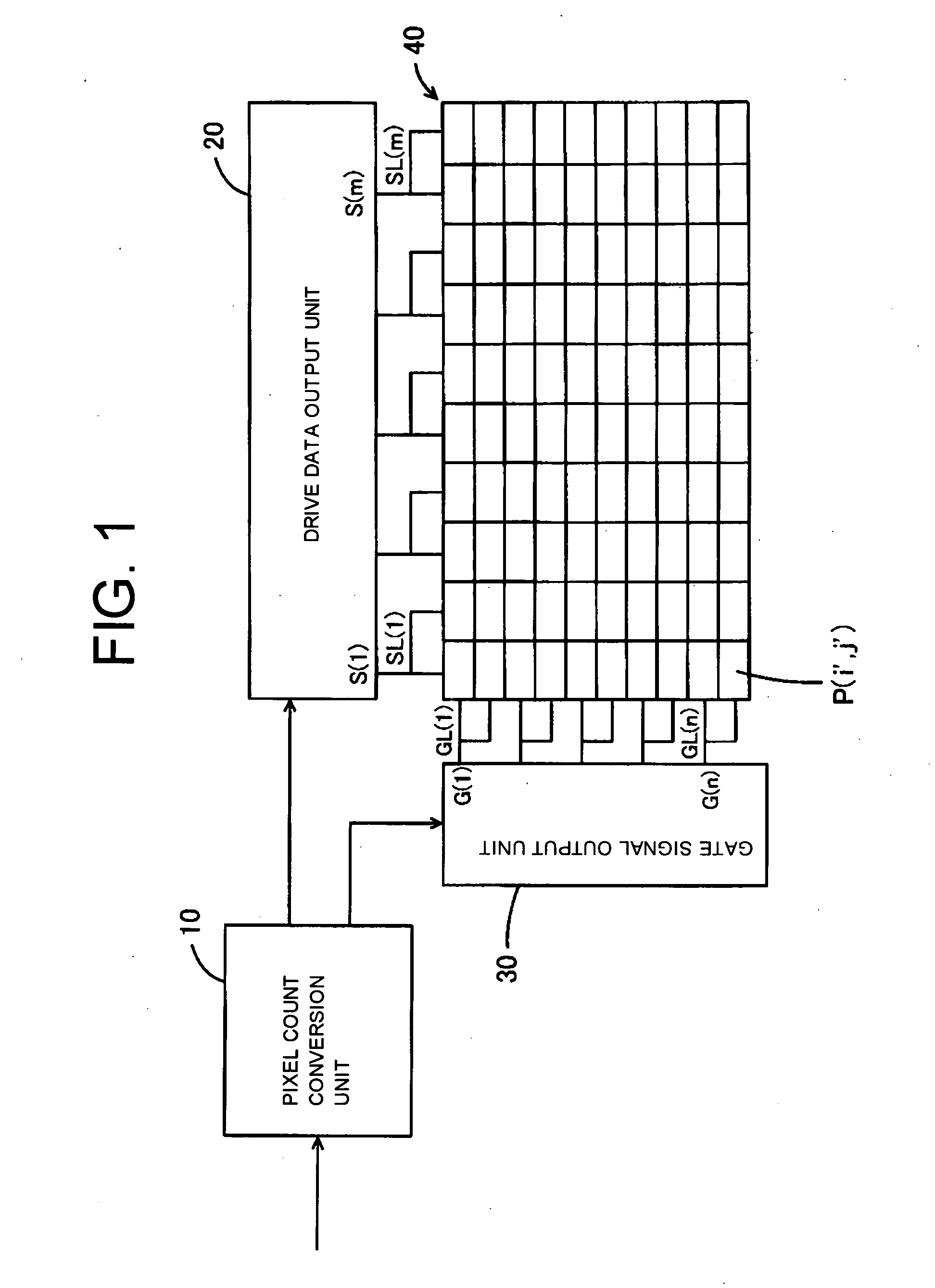
[0016]Thus, it becomes possible to drive a predetermined multiple number of pixels consecutive in the lateral direction with each drive data correspondingly to the number of branches of each of the data lines on the output side thereof, thereby reducing the number of pixels of the image data. Therefore, it is required for the pixel count conversion unit only to convert the image data so as to have the resolution lower than the number of pixels of the screen, thus it becomes possible to drive the screen with a high resolution using the pixel count conversion unit, which can only convert low resolution data. Therefore, since the maximum processing capacity required to the pixel count conversion unit is reduced, the low-priced pixel conversion unit can be used, thus the cost can be reduced.
[0017]Further, by forming a unit dot of the image with a plurality of pixels, even if a defective pixel dot occurs, the information of the image can be complemented with the remaining pixels.

Problems solved by technology

That is, since the process for expanding or shrinking the image data is performed using the demultiplexer circuit, the cost thereof rises.
Further, in the case in which the demultiplexer circuit is implemented inside the liquid crystal panel, an additional space equivalent to the size of the circuit is required, thus the liquid crystal panel is unnecessarily enlarged.
That is, since the pixel count is converted by latching (or sampling) the display data, improvement in the processing capacity of the control circuit becomes necessary, thus increasing the cost of the control circuit.

Method used


Image

  • Liquid crystal display device
  • Liquid crystal display device
  • Liquid crystal display device

Examples


Embodiment Construction

[0025]Hereinafter, some embodiments of the present invention will be explained along the following order.[0026]1. Configuration of the Liquid Crystal Display Device[0027]2. Operation and Advantages of the Liquid Crystal Display Device[0028]3. Various Modified Examples[0029]4. Conclusion

[0030]1. Configuration of the Liquid Crystal Display Device

[0031]In the present invention, a high-resolution liquid crystal screen is driven using pixel count conversion unit capable of converting only the low maximum resolution in the liquid crystal display device having a plurality of pixels filled with a liquid crystal material arranged in a matrix.

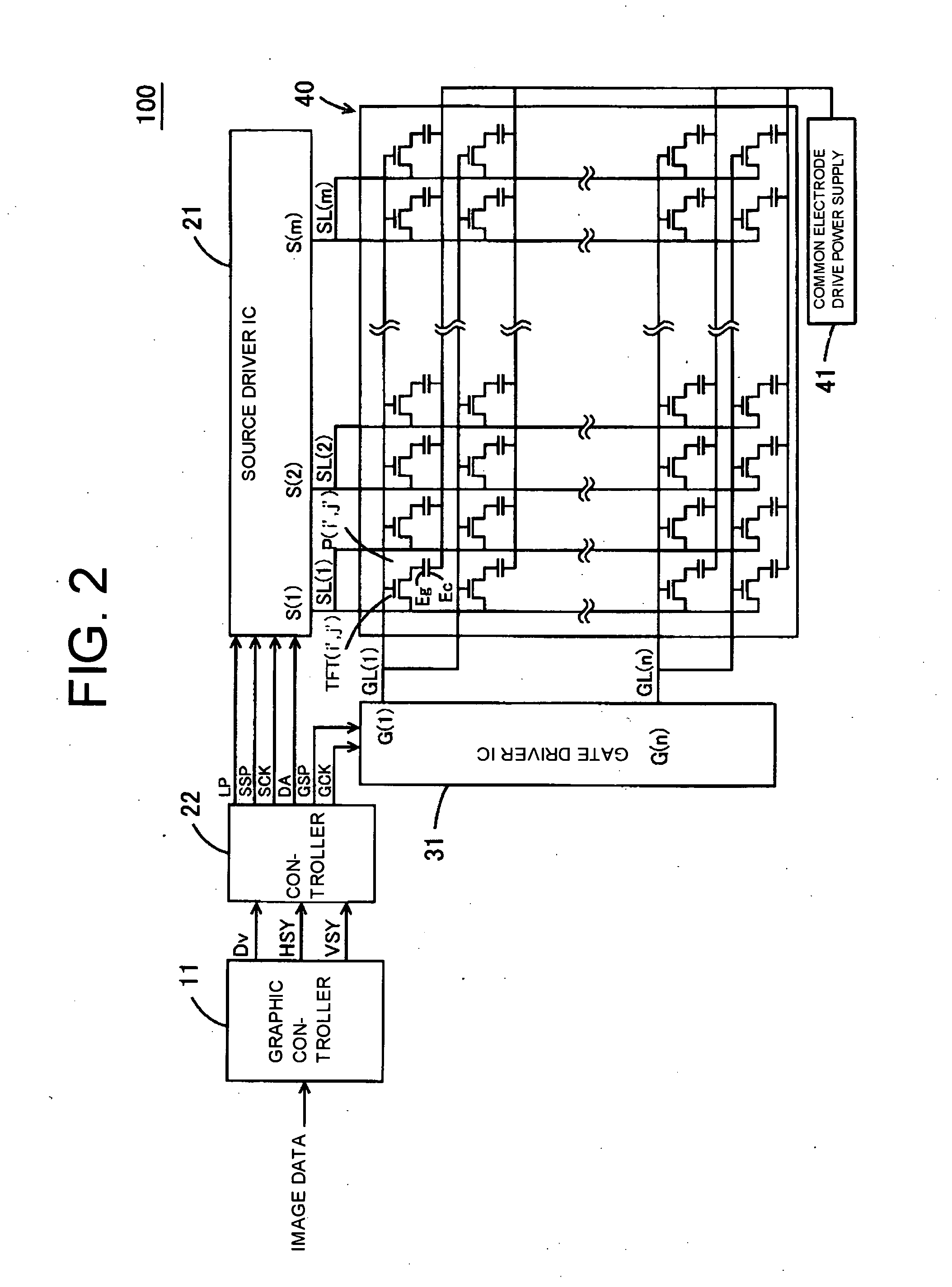
[0032]FIG. 1 is a diagram corresponding to the appended claims according to the present invention. According to the diagram, the liquid crystal display device 100 has the pixels P(i′, j′) filled with the liquid crystal material arranged in a matrix to form the screen, and inputs drive data sequentially to the pixels P(i′, j′), thereby driving the screen....


PUM


Abstract

A drive data output unit having a predetermined number of drive data output terminals arranged each for outputting the drive data; a display panel, in which the number of pixels arranged in a lateral direction is an integral multiplication of the number of drive data output terminals; a plurality of data lines connected respectively to the drive data output terminals of the drive data output unit on an input side of the data lines, and each branched to be the integral multiplication and connected respectively to the pixels consecutive in the lateral direction; gate signal output unit for specifying the pixels by line, to which the drive data are output; and pixel count conversion unit for converting the number of pixels of obtained image data into a number corresponding to the number of drive data output terminals, and supplying the drive data output unit with the converted image data.

Description

CROSS-REFERENCES TO RELATED APPLICATIONS[0001]The present application is related to the Japanese Patent Application. No. 2007-176637, filed Jul. 4, 2007, the entire disclosure of which is expressly incorporated by reference herein.BACKGROUND OF THE INVENTION[0002]1. Field of the Invention[0003]The present invention relates to a liquid crystal display device, and in particular to a liquid crystal display device, which executes pixel count conversion on image data in accordance with the resolution of the display panel.[0004]2. Description of the Related Art[0005]Liquid crystal display devices have a plurality of pixels arranged in a matrix to form a screen. In the liquid crystal devices, a unit pixel is composed of three colors of pixels RGB, and the resolution thereof is determined by the number of unit pixels forming the screen. As an example of the resolution of the screen, certain standards such as QVGA (320×240), WXGA (1366×768), and full HD (1920×1080) are set by the numbers of ...

Claims


Application Information

Patent Timeline
IPC IPC(8): G09G3/36
CPCG09G3/2096G09G3/3611G09G3/3648G09G2340/0421G09G2300/0443G09G2310/0205G09G2340/0414G09G5/005
Inventor URISU, TAKAYOSHI
Owner FUNAI ELECTRIC CO LTD
Why Eureka
Eureka Blog
Learn More