
Nullification of transmitter noise at receive signal frequency

Active Publication Date: 2009-01-08
AVAGO TECH INT SALES PTE LTD
View PDF1 Cites 3 Cited by
  • Summary
  • Abstract
  • Description
  • Claims
  • Application Information

AI Technical Summary

Benefits of technology

[0008]Nullification of transmitter noise at receive signal frequency, substantially as shown in and/or d

Problems solved by technology

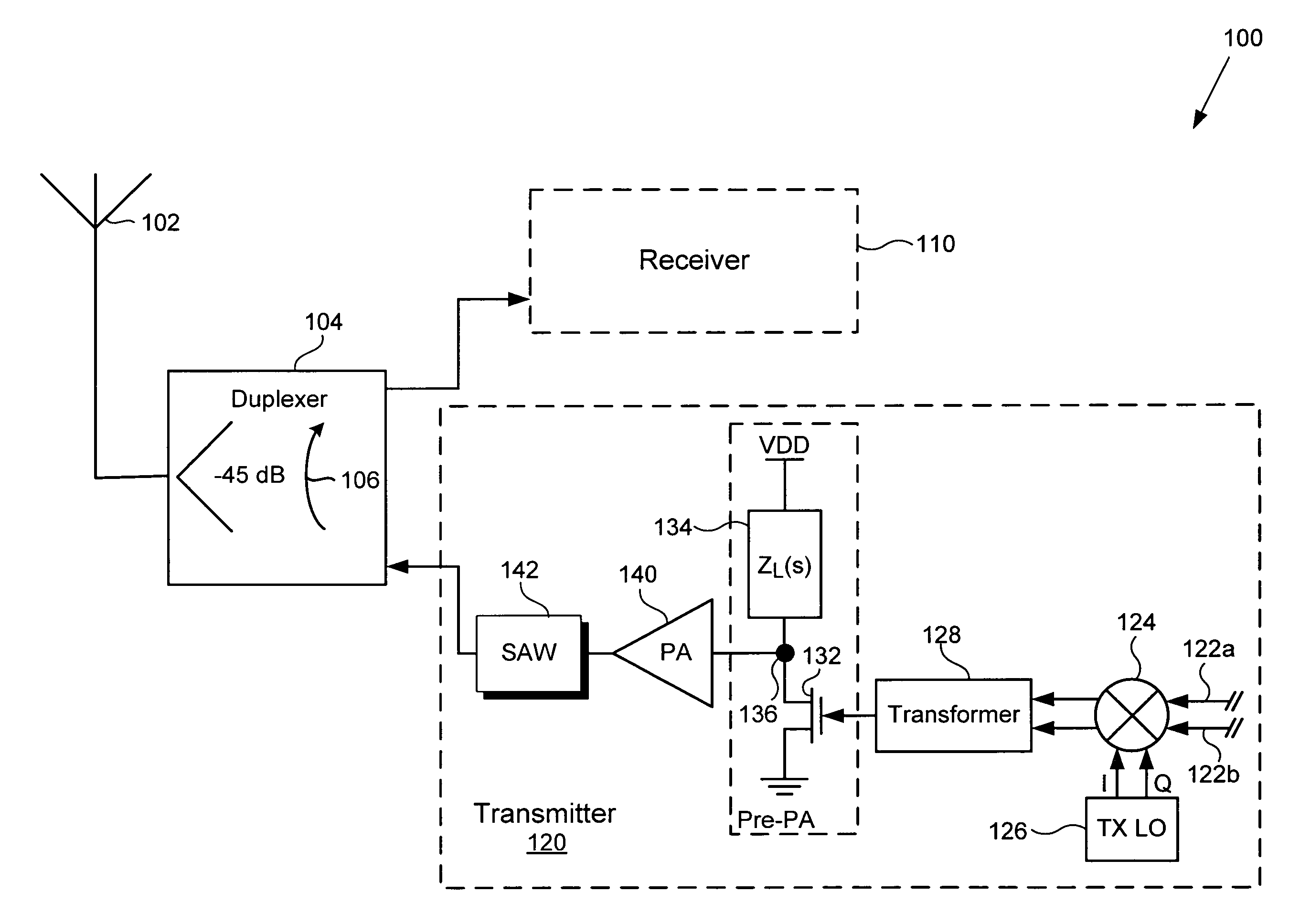
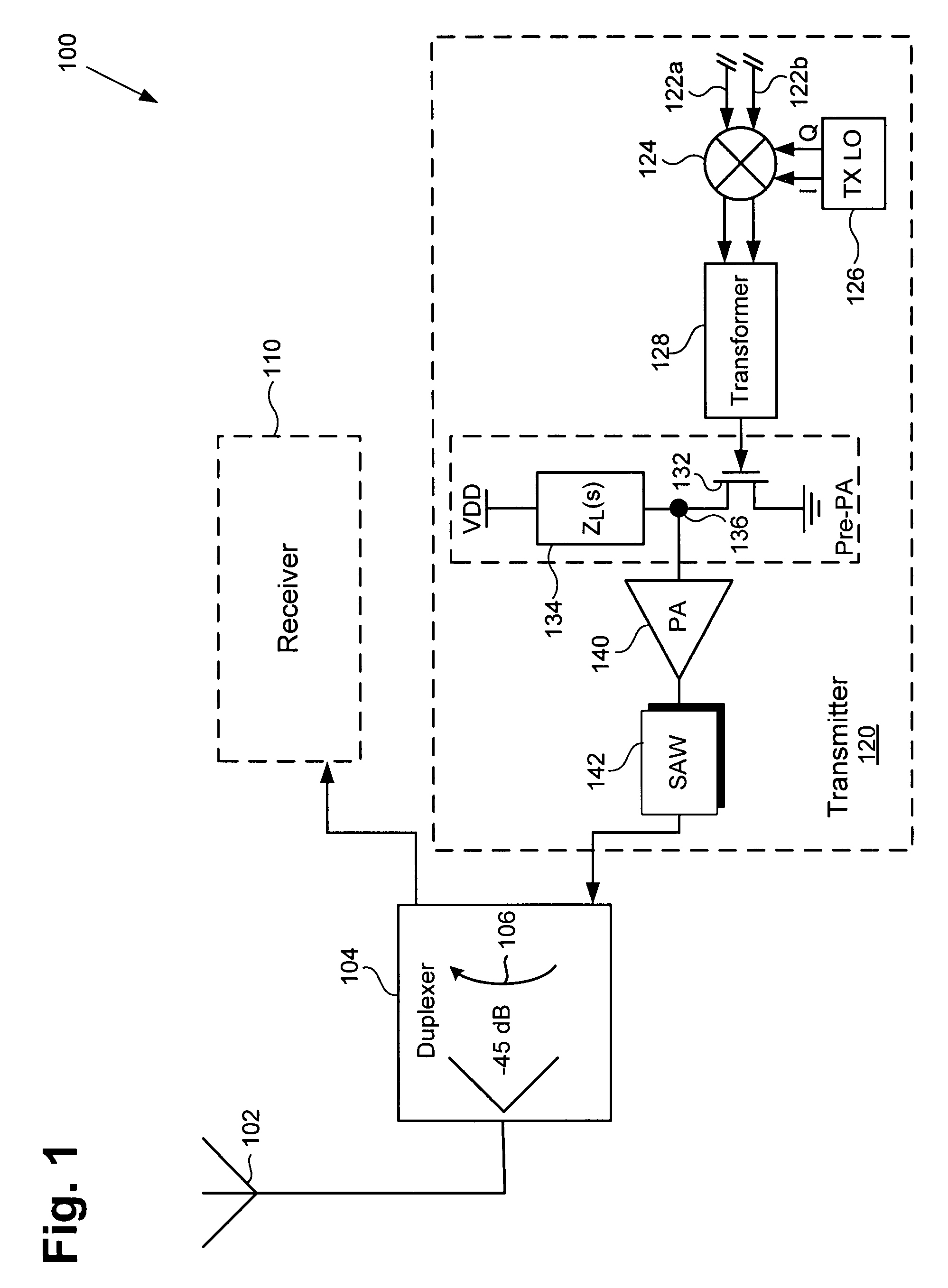
During transmit, transmission noise may be generated across a range of frequencies, including that frequency range used by the transceiver for receive signals.
Under those conditions, transmission noise, if not suppressed, may significantly interfere with reception quality.
Typically, however, while providing as much as, for example, 45 dB of attenuation, duplexers commonly in use do not completely isolate a transceiver receiver from that transceiver's transmitter.
As a result, some transmission noise may leak through the duplexer into the receiver, and this is particularly likely to occur as a transceiver's location grows more remote.
Unfortunately, these high Q filters at radio frequency are costly, and their implementation consumes a significant amount of board space.
This conventional approach has disadvantages of requiring that the mobile transceiver be equipped with a high power transmitter, and the accompanying large power consumption.
Thus, conventional approaches for suppressing transmission noise in a transceiver may require use of a high power transmitter, include implementation of a bulky and expensive SAW filter, or result in deterioration of a desired reception signal due to noise leakage through a duplexer.

Method used


Image

  • Nullification of transmitter noise at receive signal frequency
  • Nullification of transmitter noise at receive signal frequency
  • Nullification of transmitter noise at receive signal frequency

Examples


Embodiment Construction

[0016]The present invention is directed to nullification of transmitter noise at receive signal frequency. Although the invention is described with respect to specific embodiments, the principles of the invention, as defined by the claims appended herein, can obviously be applied beyond the specifically described embodiments of the invention described herein. Moreover, in the description of the present invention, certain details have been left out in order to not obscure the inventive aspects of the invention. The details left out are within the knowledge of a person of ordinary skill in the art.

[0017]The drawings in the present application and their accompanying detailed description are directed to merely exemplary embodiments of the invention. To maintain brevity, other embodiments of the invention, which use the principles of the present invention are not specifically described in the present application and are not specifically illustrated by the present drawings.

[0018]FIG. 1 is...


PUM


Abstract

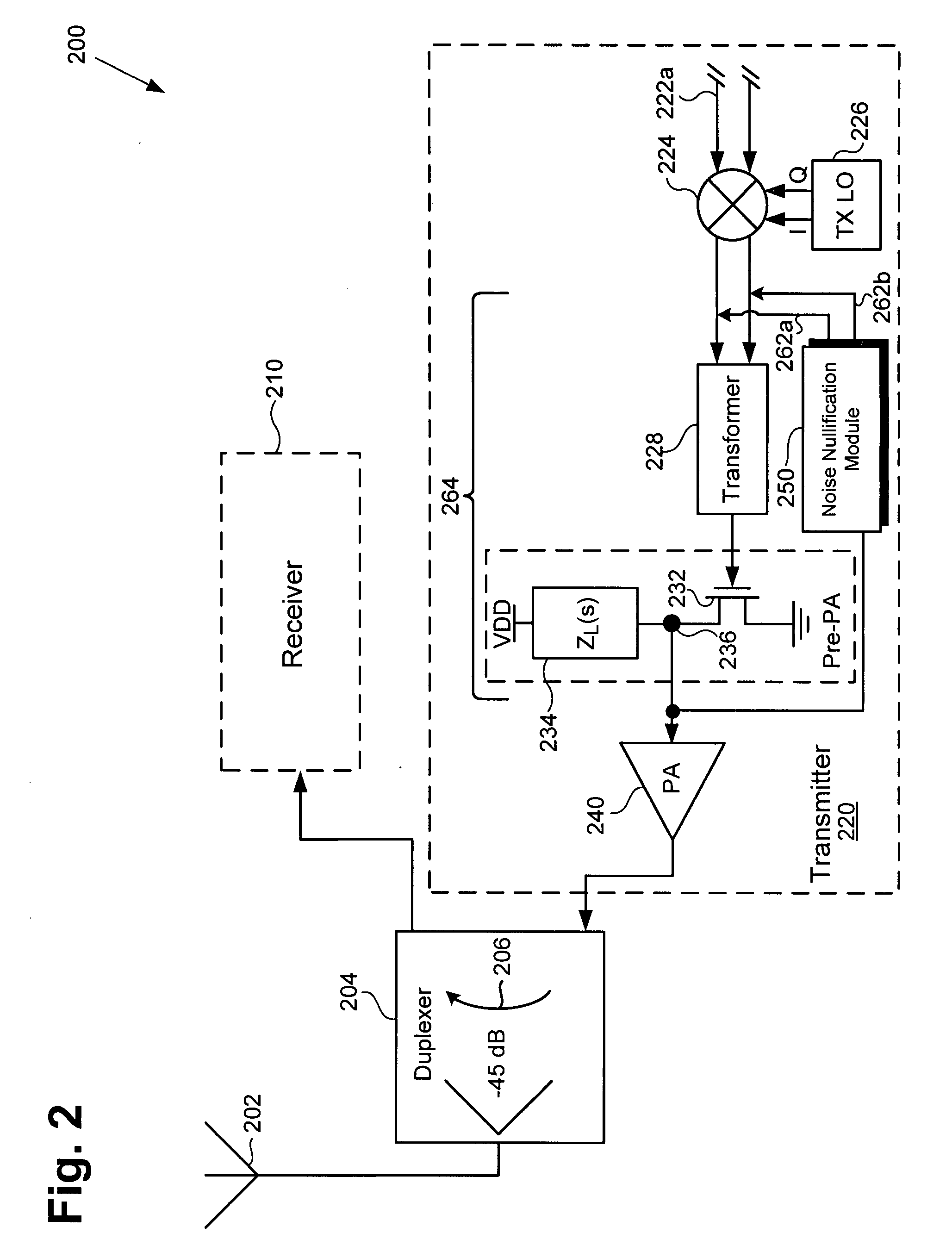
According to one exemplary embodiment, a transceiver for nullification of a noise component in a transmitter comprises a noise nullification module loading a selected node in the transmitter. The noise nullification module comprises a mixer that receives inputs from the selected node and a local oscillator, where the mixer is also coupled to a filter such that the noise nullification module presents a low impedance at an approximate frequency of a noise component so as to nullify the noise component. In one embodiment, the noise nullification module results in band-pass filtering of an approximate receive signal frequency so as to nullify a noise component at the receive frequency. In another embodiment, the noise nullification module results in notch filtering of an approximate transmit signal frequency so as to nullify a noise component at a receive signal frequency.

Description

BACKGROUND OF THE INVENTION[0001]1. Field of the Invention[0002]The present invention is generally in the field of electronic circuits and systems. More specifically, the present invention is in the field of communications circuits and systems.[0003]2. Background Art[0004]Transceivers are typically used in communications systems to support transmission and reception of communications signals through a common antenna, at radio frequency (RF) in a cellular telephone or other mobile device, for example. Often, in those devices, transmission and reception occur concurrently, at frequencies separated, for instance, by 190 MHz, 80 MHz, or as little as 45 MHz. During transmit, transmission noise may be generated across a range of frequencies, including that frequency range used by the transceiver for receive signals. In addition, during remote operation, as a mobile device is moved farther from a base-station, the strength of its transmit signal must typically increase to compensate for di...

Claims


Application Information

Patent Timeline
IPC IPC(8): H04B1/38
CPCH04B1/1036
Inventor MIRZAEI, AHMADDARABI, HOOMAN
Owner AVAGO TECH INT SALES PTE LTD
Learn More