Semi-Tight Optical Fiber Unit

a technology of optical fiber and unit, applied in the direction of optics, fibre mechanical structure, instruments, etc., can solve the problems of affecting the installation of optical cables, affecting the service life of optical cables, and requiring additional cleaning operations

Inactive Publication Date: 2009-01-08
DRAKA COMTEQ BV
View PDF15 Cites 11 Cited by
  • Summary
  • Abstract
  • Description
  • Claims
  • Application Information

AI Technical Summary

Benefits of technology

[0010]It is yet another object of the present invention to provide an optical fiber unit from which the surrounding buffer tube can be removed over a length of at least 100 centimeters without causing damage to the glass fiber or its surrounding ...

Problems solved by technology

One drawback of using grease or other gel-like material is that, during the installation of such optical modules, the grease or gel-like material tends to emerge from the optical ca...

Method used


Image

  • Semi-Tight Optical Fiber Unit
  • Semi-Tight Optical Fiber Unit

Examples


Embodiment Construction

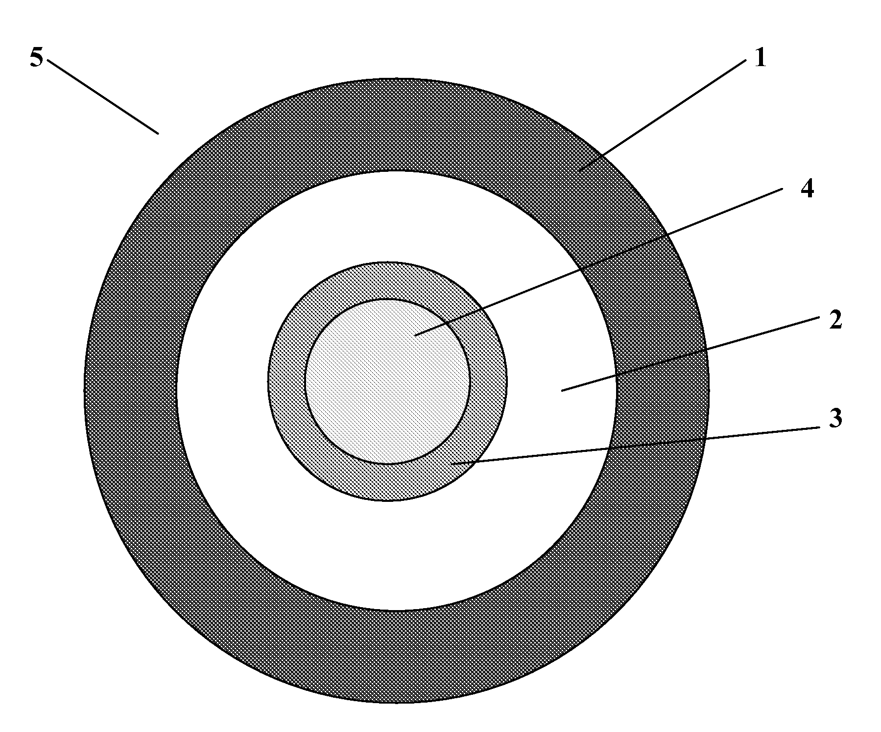
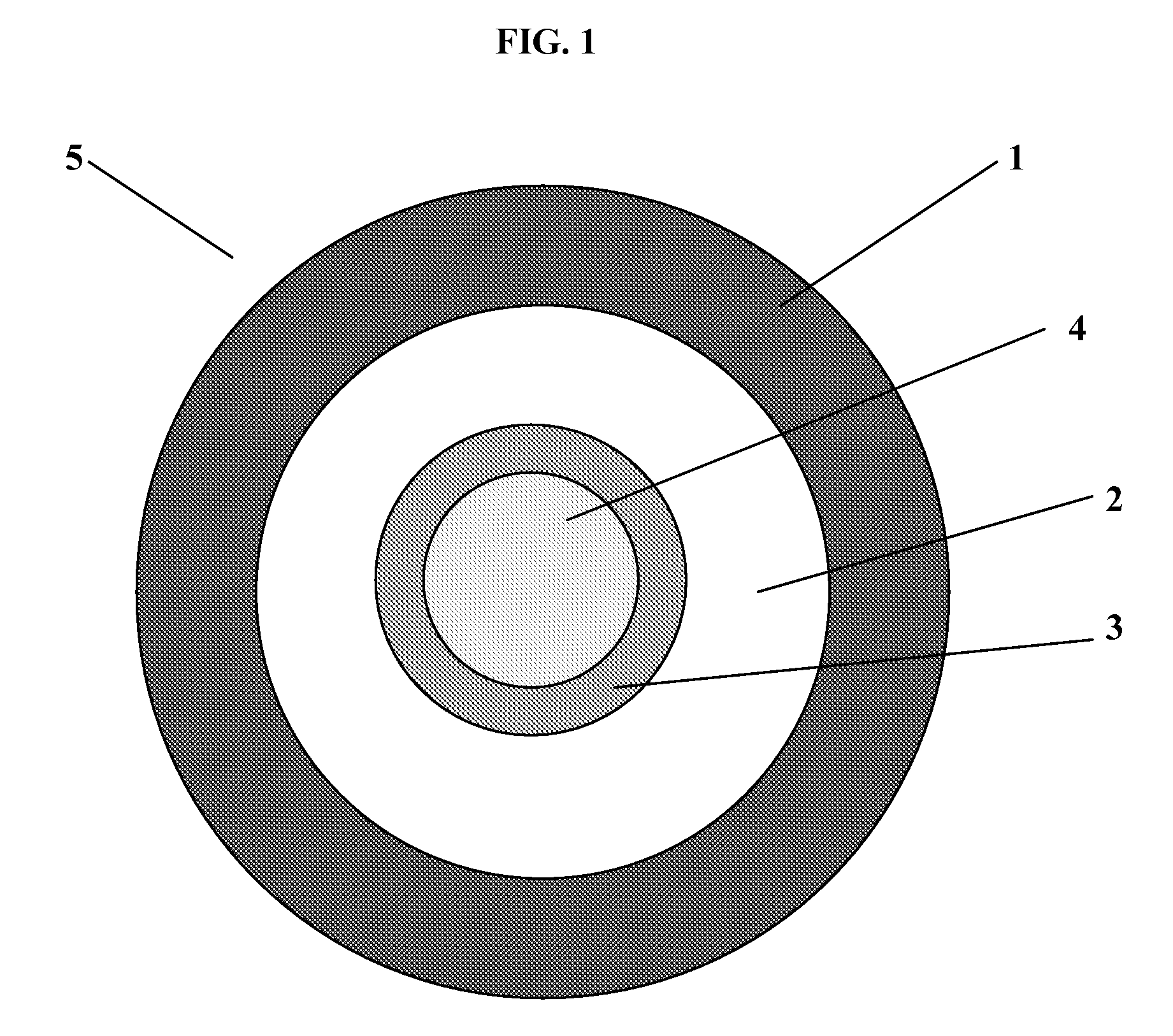
[0014]In one aspect, the present invention is an optical fiber unit that includes one or more optical fibers positioned within a buffer tube in a semi-tight or loose configuration.

[0015]As will be known by those having ordinary skill in the art, a conventional optical fiber includes a central glass fiber (e.g., a glass core and glass cladding) surrounded by one or more protective layers, such as an inner primary coating and an outer secondary coating. According to the present invention, an anti-adhesive coating envelopes (i.e., surrounds) at least one optical fiber's outermost protective layer (e.g., its secondary coating). A buffer tube loosely surrounds the one or more optical fibers (and their surrounding anti-adhesive coatings, if any). Typically, each optical fiber positioned with the buffer tube is coated with an anti-adhesive material (i.e., a non-stick layer).

[0016]In general, the minimum cross-sectional inner diameter of the buffer tube is greater than the maximum cross-sec...


PUM


Abstract

Disclosed is a dry, semi-tight optical fiber unit that includes one or more optical fibers positioned within a buffer tube. A protective coating is provided upon the surface of the optical fibers, and an anti-adhesive coating is substantially bonded to the protective coating. One or more of these optical fiber units may be included in an optical cable. Also disclosed is a method for efficiently producing such an optical fiber unit.

Description

CROSS-REFERENCE TO PRIORITY APPLICATION[0001]This application claims the benefit of pending Dutch Application No. 1033101 (filed Dec. 21, 2006, at the Dutch Patent Office), which is hereby incorporated by reference in its entirety.FIELD OF THE INVENTION[0002]The present invention relates to a semi-tight or loose optical fiber unit that includes one or more optical fibers positioned within a buffer tube. A protective coating is provided upon the surface of the optical fibers, and an anti-adhesive coating is at least partially bonded to the protective coating.BACKGROUND OF THE INVENTION[0003]U.S. Pat. No. 6,658,184, which is hereby incorporated by reference in its entirety, discloses an exemplary optical fiber module that includes a plurality of optical fibers surrounded by a flexible tube, which is referred to as a protective skin. The gaps between the optical fibers in the flexible tube are generally occupied by a hydrophobic gel. The gel not only forms a moisture barrier but also p...

Claims


Application Information

Patent Timeline
IPC IPC(8): G02B6/44
CPCG02B6/4402G02B6/4494G02B6/4438G02B6/44384
Inventor NOTHOFER, KLAUSHUIJSMAN, DICKMARIE BERKERS, ARNOLDUS GERTRUDIS WILHELMUS
Owner DRAKA COMTEQ BV
Why Eureka
Try Eureka