Stationary and dynamic radial transverse electric polarizer for high numerical aperture systems

a technology of radial transverse electric polarizer and aperture system, which is applied in the field of optical polarizers, can solve the problems of high na partially coherent system polarization targets that have not been examined, produce similar exposure changes, and tight specifications for illumination polarization of lithography tools

Inactive Publication Date: 2004-09-02
ASML NETHERLANDS BV
View PDF17 Cites 728 Cited by
  • Summary
  • Abstract
  • Description
  • Claims
  • Application Information

AI Technical Summary

Problems solved by technology

However, the polarization targets for high NA partially coherent systems have not been examined.
However, alternating phase shift masks (PSMs) require a small partial coherence which restricts the total number of angles and thus could produce similar exposure changes.
For example, high NA polarization effects may result in extremely tight specifications on illumination polarization for lithography tools.
However, as stated above, higher NA may result in extremely tight specifications on illumination polarization for lithography tools.
Use of birefringent polarizers is characterized by inefficiency, wavelength dependent performance and requires highly collimated light.
Stretched polymer polarizers degrade with time as the light induces chemicals changes in the polymeric material resulting in the material becoming yellow or brittle.
Dichroic polarizers are also sensitive to heat and other environmental changes.
One problem with this polarizer technique is its low extinction ratio of approximately 15.
While useful for some applications, this extinction ratio is not adequate for imaging applications without a secondary polarizer.
This type of polarizer also suffers from the environmental problems discussed above.
Thin film polarizer technology however limits the angular range of the light beam incidence.
Thin film polarizer technology also suffers from the wavelength dependence because of the dependence of Brewster's angle on the wavelength of the incident light.
Otherwise the loss of contrast would be severe enough to destroy any viable imaging.
Therefore, the use of circular polarization would not lead to interference lines and consequently is not suitable for high resolution imaging for lithographic systems because in the wafer plane circular polarization is reduced to linear polarization and the drawbacks of this were described above in this paragraph.

Method used


Image

  • Stationary and dynamic radial transverse electric polarizer for high numerical aperture systems
  • Stationary and dynamic radial transverse electric polarizer for high numerical aperture systems
  • Stationary and dynamic radial transverse electric polarizer for high numerical aperture systems

Examples


Embodiment Construction

unpolarized immersion lithographic system imaging 50 nm dense lines. The wavelength of use in this example is 193 nm. The immersion fluid used is water with a refractive index of 1.437 (NA=1.437). The air equivalent numerical aperture NA is 1.29. The resist used in this example is Par710 on a matched substrate. The illumination is annular with .sigma.=0.9 / 0.7. FIG. 5 is a plot of the exposure latitude versus depth of focus for comparative Example 1. This plot indicates that the exposure latitude at a depth of focus of 0.0 is approximately 5.6%, which is an unusable level. At other depth of focus the exposure latitude decreases even more which makes an unpolarized light unusable in lithographic system at high NA.

[0080] FIG. 6 shows the process window for a 50 nm dense lines with TE polarized light and immersion optics according to an Example 1 of the present invention. The wavelength of use in this example is 193 nm. The immersion fluid used is water with a refractive index of 1.437 ...


PUM

PropertyMeasurementUnit
wavelength rangeaaaaaaaaaa
wavelengthsaaaaaaaaaa

Abstract

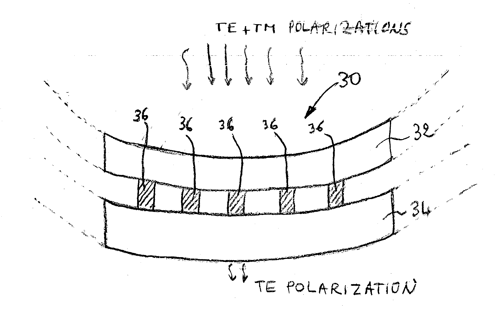
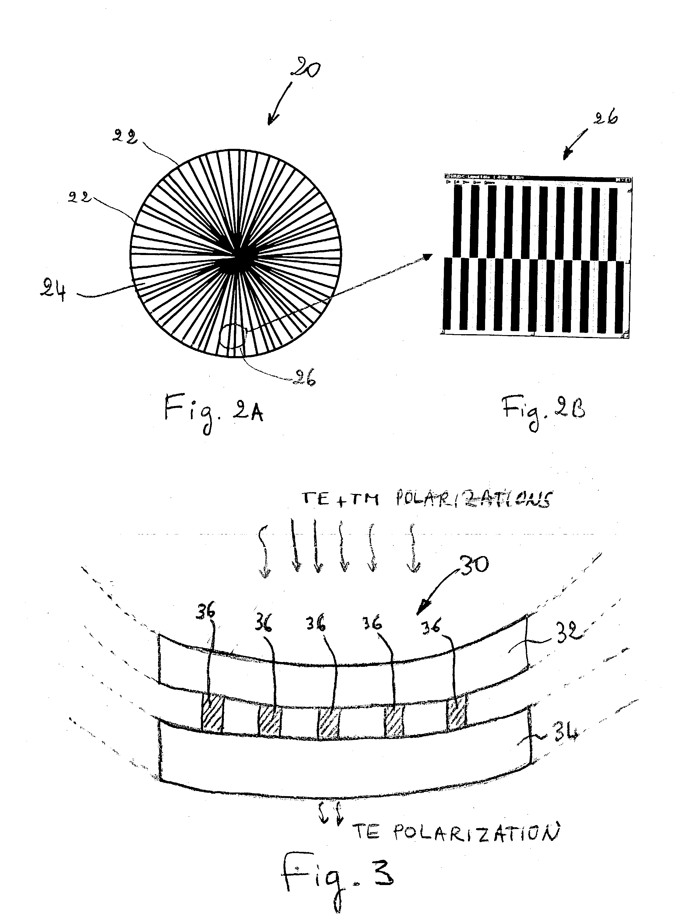
A radial transverse electric polarizer device is provided. The device includes a first layer of material having a first refractive index, a second layer of material having a second refractive index, and a plurality of elongated elements azimuthally and periodically spaced apart, and disposed between the first layer and the second layer. The plurality of elongated elements interact with electromagnetic waves of radiation to transmit transverse electric polarization of electromagnetic waves of radiation. One aspect of the invention is, for example, to use such polarizer device in a lithographic projection apparatus to increase imaging resolution. Another aspect is to provide a device manufacturing method including polarizing a beam of radiation in a transverse electric polarization.

Description

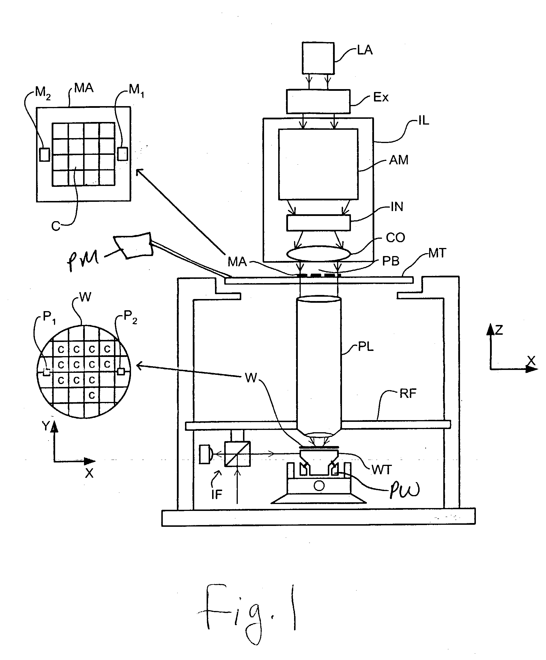
[0001] 1. Field of the Invention[0002] The present invention relates to optical polarizers in general and more particularly to polarizers for high numerical aperture lithography.[0003] 2. Background of the Invention[0004] A lithographic projection apparatus can be used, for example, in the manufacture of integrated circuits (ICs). In such a case, a patterning device generates a circuit pattern corresponding to an individual layer of the IC, and this pattern can be imaged onto a target portion (e.g. comprising one or more dies) on a substrate (silicon wafer) that has been coated with a layer of radiation sensitive material (resist). In general, a single wafer or substrate will contain a whole network of adjacent target portions that are successively irradiated via the projection system, one at a time.[0005] The term "patterning device" as here employed should be broadly interpreted as referring to device that can be used to endow an incoming radiation beam with a patterned cross-sect...

Claims


Application Information

Patent Timeline
Patent Type & Authority Applications(United States)
IPC IPC(8): G02B5/30G03F7/20H01L21/027
CPCG03F7/70566G02B5/3058
Inventor FLAGELLO, DONISCUMMINGS, KEVINSTRAAIJER, ALEXANDER
Owner ASML NETHERLANDS BV
Why Eureka
Try Eureka