High numerical aperture fiber

a technology of optical fibers and apertures, applied in the direction of optical fibers with polarisation, optical waveguide light guides, instruments, etc., can solve the problems of shortening the life of devices, and affecting the performance of devices

Inactive Publication Date: 2008-07-31
CORNING INC
View PDF14 Cites 57 Cited by
  • Summary
  • Abstract
  • Description
  • Claims
  • Application Information

AI Technical Summary

Benefits of technology

[0011]One aspect of the invention is an active optical fiber comprising: a silica based core having a first index of refraction n1; and at least one silica based cladding surrounding the core, the at least one silica based cladding having a second index of refraction ni, such that n1>ni; the at least one silica based cladding comprises non-periodic index lowering voids containing gas, wherein at least 80% of said voids

Problems solved by technology

owever, at higher temperatures, PCS of optical fiber heats and the polymer material of the outer cladding layer carbonizes or burns, resulting in device failure, especially when the fiber is bent. E
ven at the temperatures between 85° C. and 125° C., the polymer cladding ages relatively quickly, losing its mechanical and optical characteristics and becoming brittle, thus shortening the device life. F
inally, both of these types of fiber suffer from bend losses.
This type of fiber has low capability of handling high power multimode optical sources due to the difficulty of efficiently coupling multimode light from a high power optical (light) source (also referred to herein as optical pump or pump) into the rare-earth doped fiber core.
Such

Method used


Image

  • High numerical aperture fiber
  • High numerical aperture fiber
  • High numerical aperture fiber

Examples


example 1

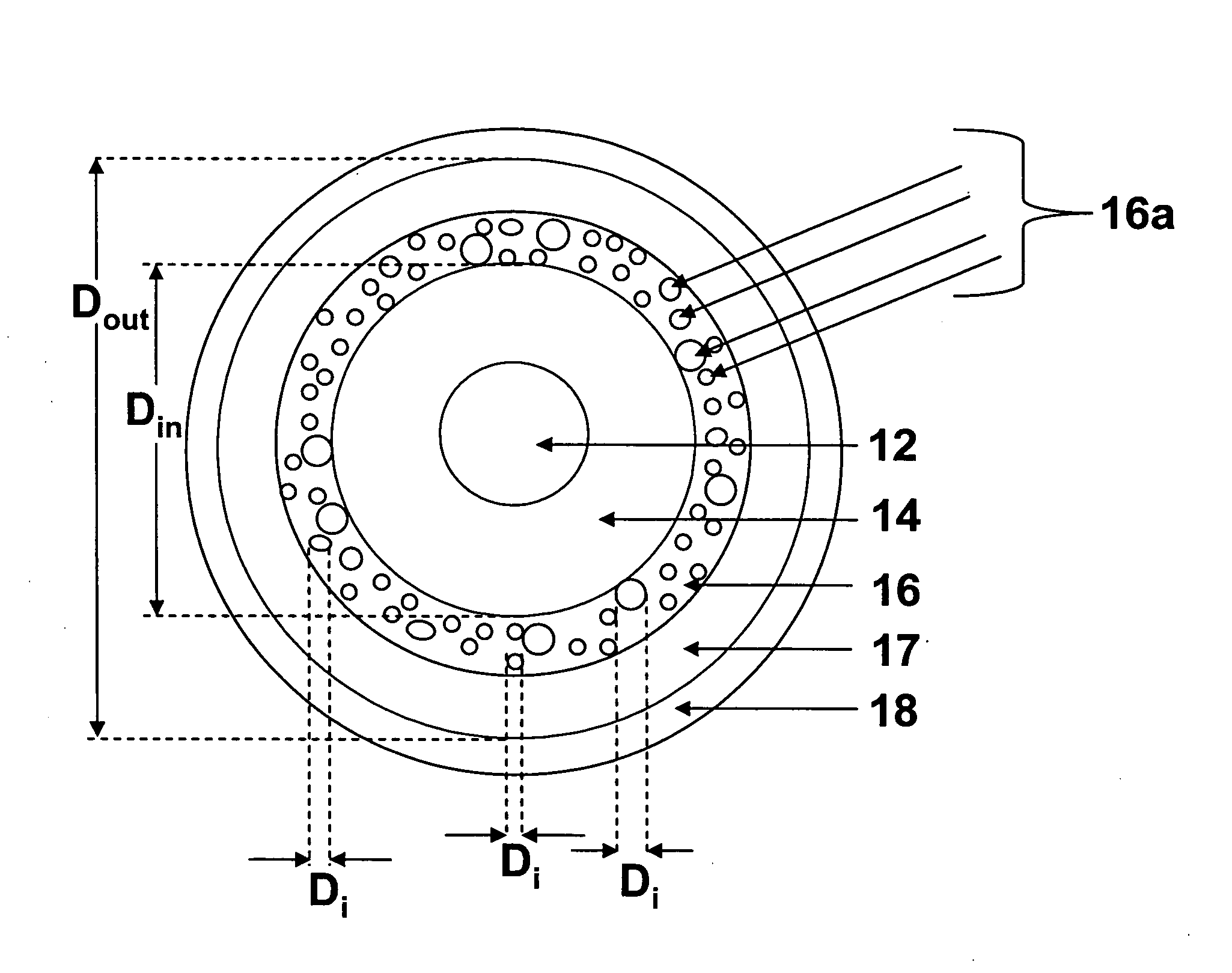
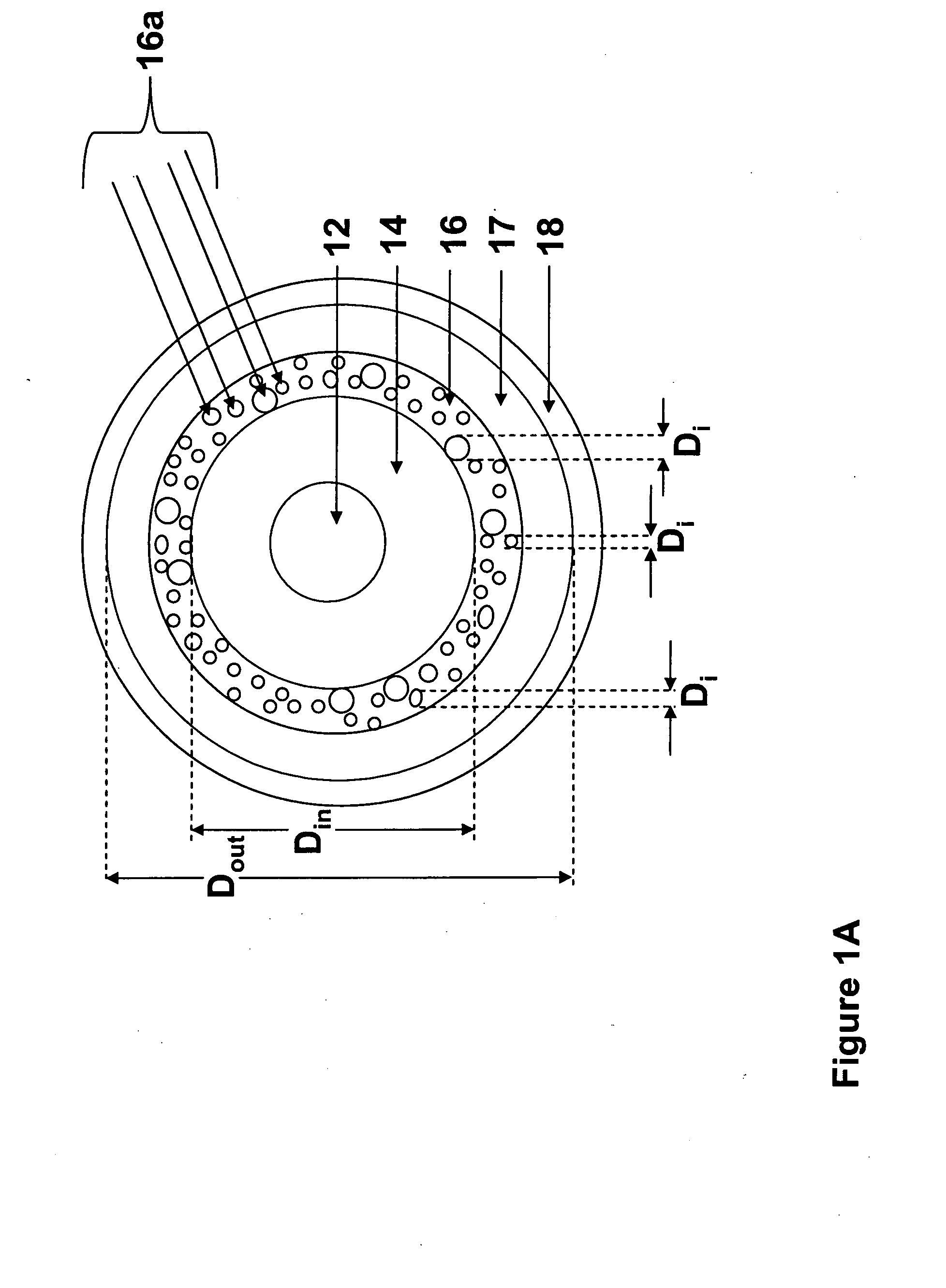
[0046]The optical fiber 10 of example 1 is illustrated schematically in FIGS. 1A and 1B and has a Yb doped core 12, a GeO2-silica inner cladding (refractive index % delta≈0.46) and an outer cladding 16 which doped with fluorine and boron. The refractive index percent (%) delta is defined herein as (ni2−ns2) / 2ni2, where i=1, 2 or 3, and ns is the refractive index of pure silica. The relative refractive index difference (percent delta) of the core 12 (relative to the inner cladding 14) is about 0.56. The outer cladding 16 of this fiber is fluorine / boron doped and comprises N2 containing voids (16% porosity). The Yb-doped fiber core 12 is single-mode for the wavelengths above 1 μm. If the core 12 is doped with Erbium, the optical fiber will be single-mode at lasing wavelength of 1.55 μm. The optical fiber 10 has a relatively low NA (about 0.065) for the core 12, and high NA (0.39, measured at 1380 nm wavelength) for the inner cladding 14. This inner cladding NA is preferably higher tha...

example 2

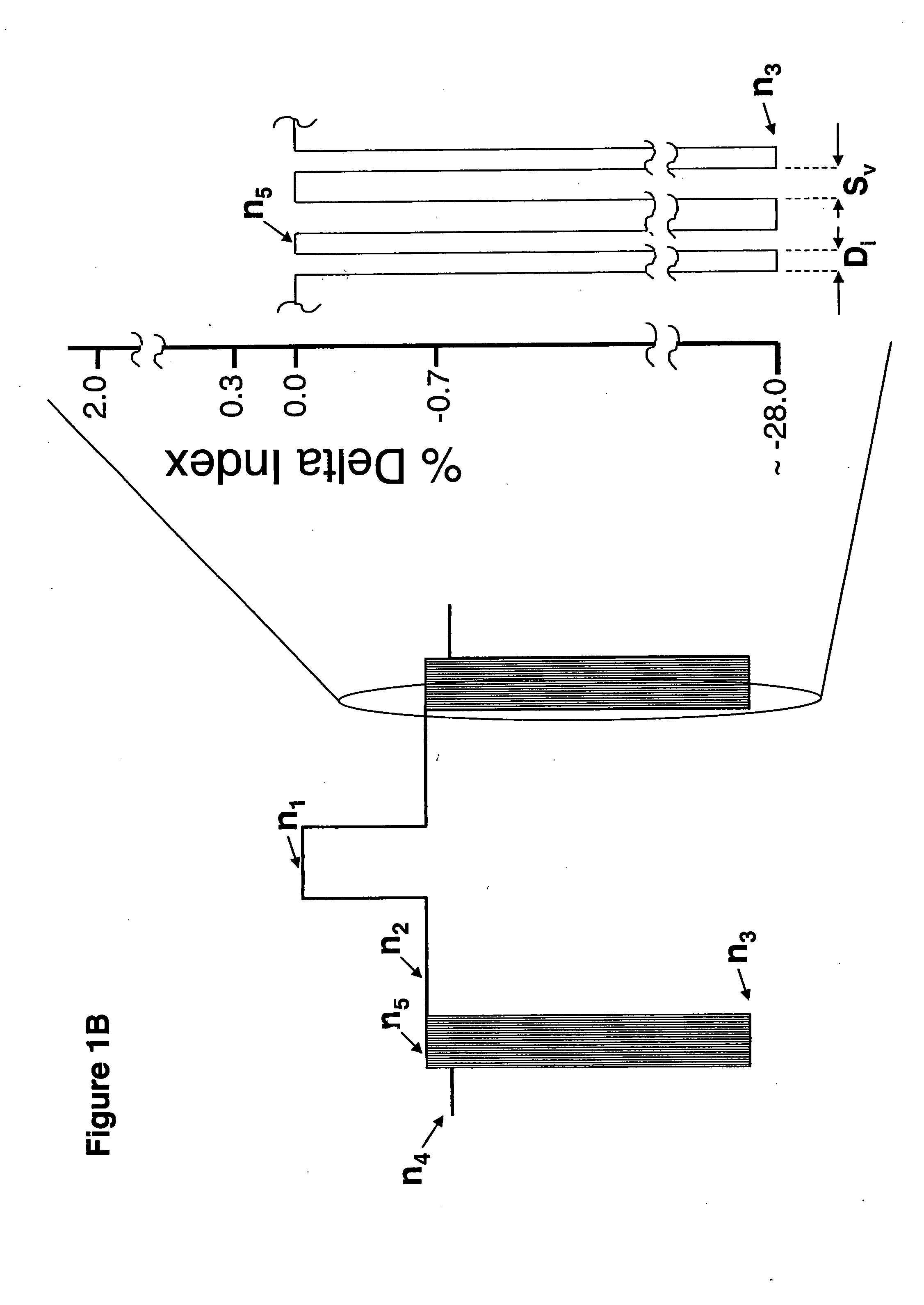
[0051]This optical fiber of this example is illustrated schematically in FIGS. 1A and 1B and has a Yb doped, silica based core 12 which is multi mode at the lasing wavelength of 1100 μm, a pure silica based inner cladding 14 (delta %≈0) and a pure silica outer cladding 16 with 16% porosity in the void (argon gas) containing region. In this example, the relative refractive index deltas n5 and n3 are about 0% and −28%, respectively (relative to pure silica). The NA of the inner cladding 14, is 0.3 (measured at 1380 nm). The refractive index difference (delta %) of the core 12 relative to the inner cladding, 14, is about 0.7. The core 12 and the first section of the inner cladding 14 are produced by an inside-vapor-deposition (IVD) process. The core GeO2—SiO2 soot is deposited inside the glass tube (first section of the inner cladding) and followed by solution Yb-doping of the core soot. The structure is then sintered into a solid preform. The preform is then used as a bait-rod for the...

example 3

[0056]This active optical fiber of example 3 (also illustrated schematically in FIGS. 1A and 1B) has a Yb doped core 12, a silica based, GeO2 doped silica inner cladding 14 having an NA of 0.3 (measured at 1380 nm), and voids containing outer cladding 16 which is doped with Fluorine and Boron. The refractive index difference (% delta) of the core 12 (relative to the inner cladding) is about 0.7. The specific composition for this optical fiber example is:[0057]Core 12: 0.8 wt % Yb2O3; 9.5 wt % P2O3; 5.4 Wt % GeO2;[0058]Inner cladding 14: 6 Wt % GeO2;

[0059]Outer cladding 16: 9 wt % B and 2.7 wt % F, with 5% porosity (argon containing voids) within the outer cladding with a mean hole size of 300 nm and a standard deviation of 150 nm. In this example, the relative refractive index deltas n5 and n3 are about −1.5% and −28%, respectively (relative to pure silica). The gas filled voids 16A improve the NA of the inner cladding 16 and thus provide a much higher laser pump efficiency, and sin...


PUM


Abstract

An optical fiber comprising: a silica based core having a first index of refraction n1; and at least one silica based cladding surrounding the core, the at least one silica based cladding comprising index lowering non-periodic voids containing a gas, wherein at least 80% of said voids have a maximum cross-sectional dimension of less than 2000 nm, and the NA of the fiber layer situated immediately adjacent to and inside said at least one silica based cladding is at least 0.2.

Description

BACKGROUND OF THE INVENTION[0001]1. Field of the Invention[0002]The present invention relates generally to high NA optical fibers, including fibers with high NA large cores for short distance communication systems, or with high NA claddings in double clad fibers for use with high power light sources or in optical fiber lasers and optical amplifiers.[0003]2. Technical Background[0004]Optical fiber has become a favorite medium for telecommunications due to its high capacity and immunity to electrical noise. Optical fibers have also been utilized in automotive applications because they offer high bandwidth, are relatively inexpensive, and can be used in automotive optical data systems to provide optical data for information system, entertainment, engine management and safety systems. Such fibers require high numerical aperture of the fiber core and a large core, to provide for efficient coupling of light into the fiber core. Two types of optical fiber are now utilized in automotive app...

Claims


Application Information

Patent Timeline
IPC IPC(8): G02B6/02G02B6/036
CPCG02B6/02366G02B6/03633G02B6/024
Inventor BOOKBINDER, DANA CRAIGLI, MING-JUNMURTAGH, MICHAEL THOMASNOLAN, DANIEL ALOYSIUSTANDON, PUSHKARWANG, JI
Owner CORNING INC
Why Eureka
Try Eureka