
Electrically-Driven Compressor

Inactive Publication Date: 2009-01-08
TOYOTA IND CORP
View PDF16 Cites 22 Cited by
  • Summary
  • Abstract
  • Description
  • Claims
  • Application Information

AI Technical Summary

Benefits of technology

[0008]It is an object of the present invention to provide an electrically-driven compressor that does not require a means for sustaining the shape of, a seal in the housing and the cover member while easily ensuring adhesion between the housing and the cover member.

Problems solved by technology

However, when the electrical components contact the cover member, a gap is formed between the open end of the cover member and the circuit board.
If the cover member is manufactured with low accuracy, the adhesion of the open end of the cover member to the gasket decreases, and dust and moisture enters the cover member from the space between the cover member and the circuit board.

Method used


Image

  • Electrically-Driven Compressor
  • Electrically-Driven Compressor
  • Electrically-Driven Compressor

Examples


first embodiment

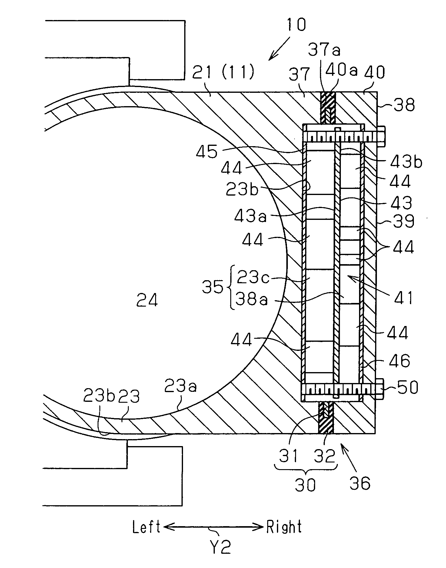
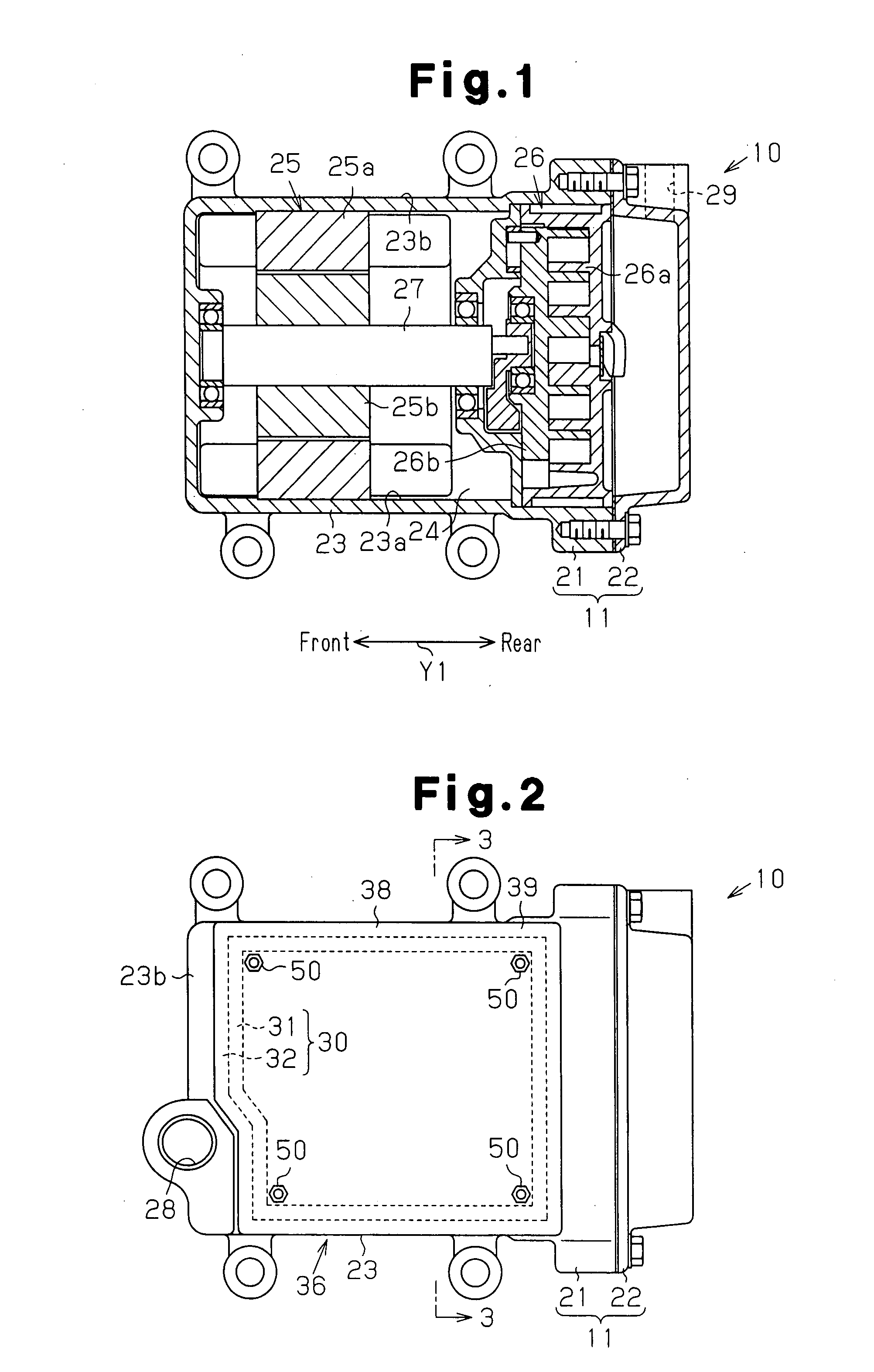
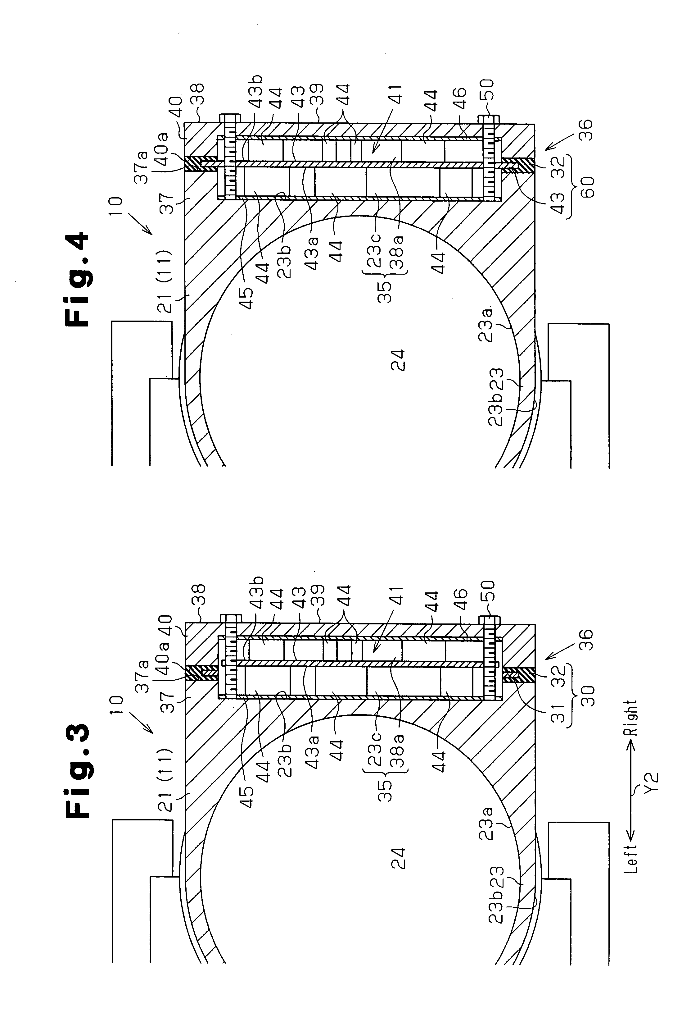
[0025]the present invention will now be described with reference to FIGS. 1 to 3. In the following description, the “front” and “rear” of the compressor correspond to the directions of the arrow Y1 shown in FIG. 1, and the “left” and “right” correspond to the directions of the arrow Y2 shown in FIG. 3.

[0026]As shown in FIG. 1, a housing 11 forming the outer shell of an electrically-driven compressor 10 includes a first housing element 21 and a second housing element 22. The second housing element 22 is joined and fixed to the rear end of the first housing element 21. The first housing element 21, which is formed by die casting aluminum alloy, has a bottom located at the front end of a substantially cylindrical circumferential wall 23. The second housing element 22, which is formed by die casting aluminum alloy, is cylindrical and has a lid located at the rear end. A sealed space 24 is formed between the first housing element 21 and the second housing element 22.

[0027]The first housi...

second embodiment

[0048]As shown in FIG. 4, a sealing member 60 of the second embodiment is formed with the seal portion 32 integrated with a circumferential edge part of a circuit board 43, which has the shape of a four-side plate, in the motor drive circuit 41. That is, the circumferential edge part of the circuit board 43 is also used as the shape sustaining member for sustaining the seal portion 32 in the shape conforming to the open ends 37a and 40a.

[0049]Accordingly, the present embodiment has the following advantage in addition to the advantages similar to advantages (1) to (5) of the first embodiment.

[0050](8) The sealing member 60 is formed by integrating the seal portion 32 with the circuit board 43 of the motor drive circuit 41. Thus, the seal portion 32 may be arranged at the circumferential edge of the accommodation space 35 at the same time when arranging the motor drive circuit 41 in the accommodation space 35. Thus, in the present embodiment, the task for forming the accommodation po...

third embodiment

[0052]As shown in FIG. 5, the accommodation portion 36 is arranged on the upper part of the circumferential wall 23 of the first housing element 21 in the That is, the accommodation portion 36 includes the side wall 37 of four-sided frame shape integrally extended from the outer surface 23b (upper surface in FIG. 5) of the circumferential wall 23, and a cover member 38 attached and fixed to the side wall 37. The sealing member 30 is arranged between the open end 37a of the side wall 37 in the housing 11 and the open end 40a of the circumferential wall portion 40.

[0053]As shown in FIG. 6, the sealing member 30 is formed to have a four-sided frame shape and arranged along the circumferential edge of the accommodation space 35. The sealing member 30 includes the core 31, which serves as a shape sustaining member having the shape of a generally four-sided frame, and a seal portion 32, which is made of a rubber material integrated with the core 31. The sealing member 30 has an outline f...


PUM


Abstract

An electrically-driven compressor including a housing, an electric motor, a compression mechanism, a cover member, a motor drive circuit, and a sealing member is disclosed. The electric motor is accommodated in the housing. The compression mechanism is accommodated in the housing and operated by the electric motor. The cover member is attached to the housing. The housing and the cover member form an accommodation portion including an accommodation space therein. The motor drive circuit is accommodated in the accommodation space and drives the electric motor. The sealing member is arranged between the housing and the cover member to seal the accommodation space. The sealing member includes an elastic seal portion that comes into close contact with the housing and the cover member. A core sustains the shape of the seal portion in conformance with the circumferential edge of the accommodation space. The core is formed so that at least a circumferential edge part of the core is in conformance with the circumferential edge of the accommodation space. The seal portion is formed integrally with the circumferential edge part of the shape sustaining member by depositing rubber material thereon.

Description

TECHNICAL FIELD[0001]The present invention relates to an electrically-driven compressor including a compression mechanism driven by an electric motor, and more particularly, to an electrically-driven compressor in which a drive circuit for driving an electric motor is accommodated in an accommodation portion of a housing.BACKGROUND ART[0002]This type of electrically-driven compressor is disclosed in, for example, patent document 1. In the electrically-driven compressor disclosed in patent document 1, a scroll type compression mechanism and a motor (electric motor) for driving the compression mechanism are accommodated in a casing (housing) that forms the outer shell of the electrically-driven compressor. The motor, which is operated by the control of an inverter controller, drives the compression mechanism. A tubular wall having a tubular shape projects from the upper part of the casing, and a cover member is fastened by bolts to an open end of the tubular wall with a circuit board ...

Claims


Application Information

Patent Timeline
IPC IPC(8): F04B39/12F04B17/03F16J15/06
CPCF01C21/10F04C18/0215F16J15/125F04C2240/30F04C2240/808F04C27/008F04C27/003F16J15/022F16J15/061F16J15/062F16J15/104F16J15/121F16J15/122H02K5/22H02K5/225
Inventor KOIDE, TATSUYASUITOU, KENKIMURA, KAZUYAFUJII, AKIOTAKETANI, AKIHIKOIGUCHI, MASAOMOCHIZUKI, KENJIENAMI, SHINGO
Owner TOYOTA IND CORP
Learn More