
Display device and adhesion method of 3D cover glass

Inactive Publication Date: 2020-05-07
WUHAN CHINA STAR OPTOELECTRONICS SEMICON DISPLAY TECH CO LTD
View PDF0 Cites 0 Cited by
  • Summary
  • Abstract
  • Description
  • Claims
  • Application Information

AI Technical Summary

Benefits of technology

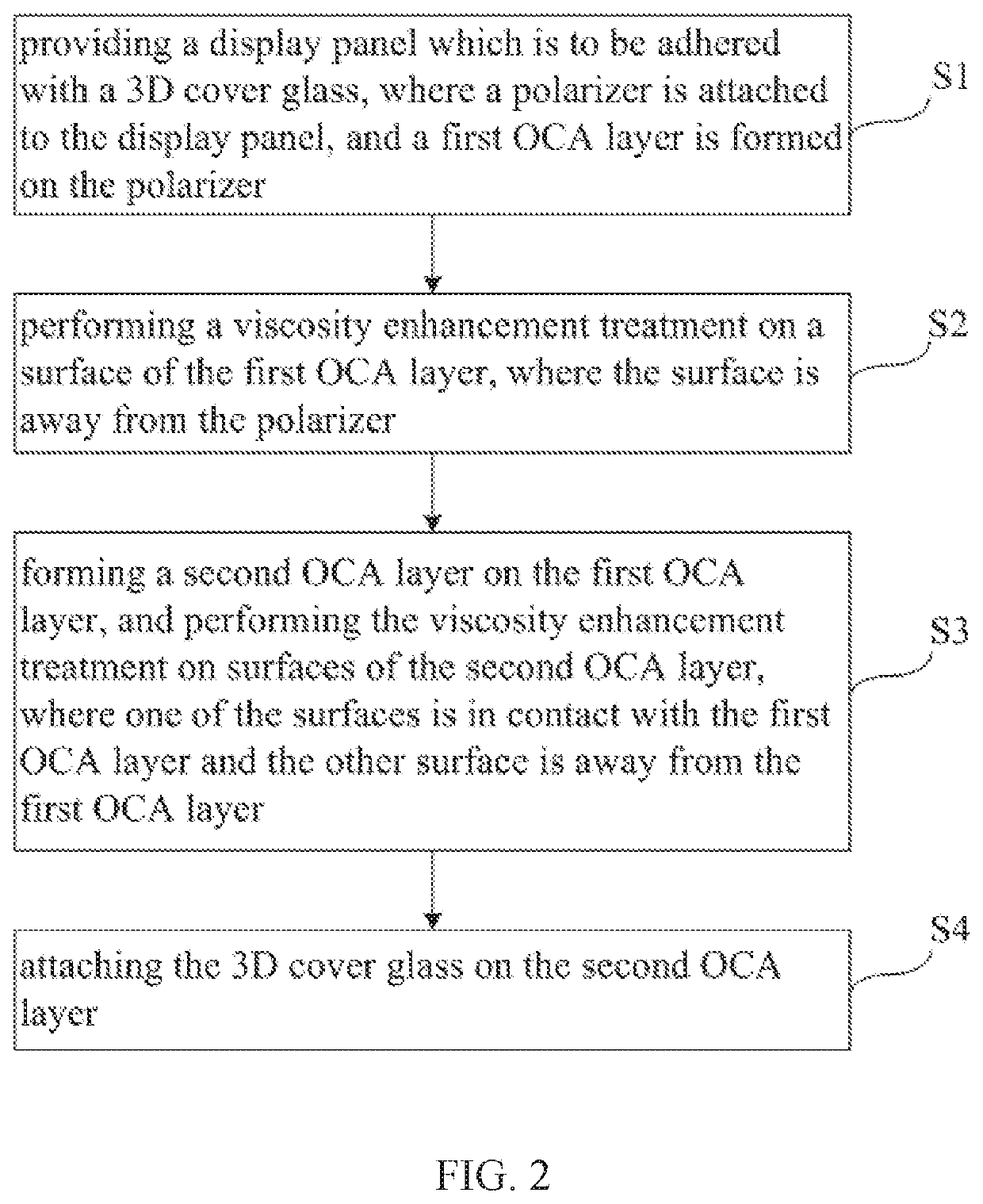
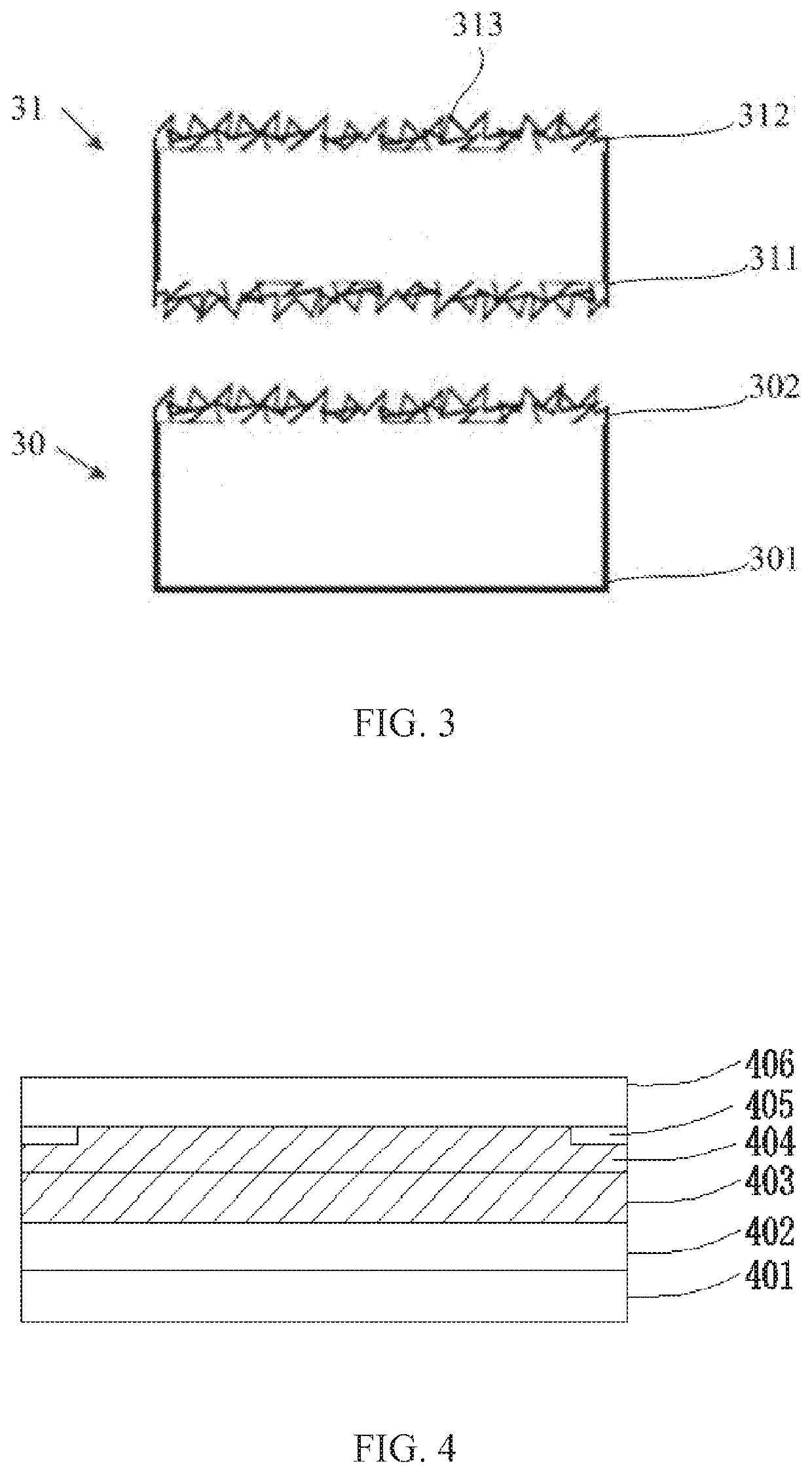
This patent describes a new method for adhering a 3D cover glass to a display device using a double-layer structure with smooth surfaces. The method also includes a viscosity enhancement treatment to ensure easy separation of the cover glass without damaging the display screen. The technical effect is that this new method reduces the cost of use and maintenance for consumers and allows for easier re-working in case of damage to the screen.

Problems solved by technology

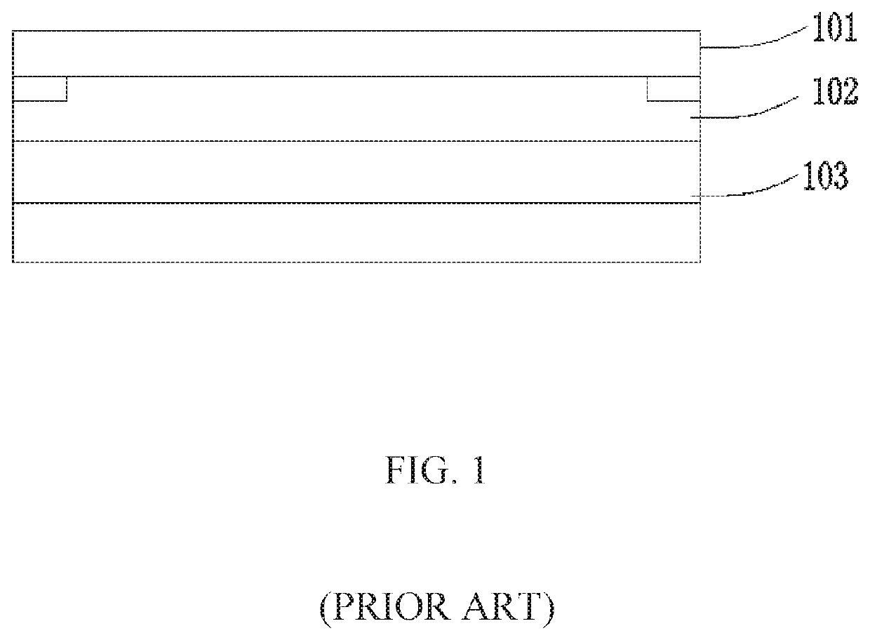
However, the 3D cover glass has a significant drawback, it is easy to break when dropped, especially in the edge part with arc.
Therefore, for a consumer, a maintenance cost will become higher.
Therefore, it is difficult to rework after adhering.
Even if the 3D cover glass 101 is forcibly separated from the screen 103 by heating, freezing, or the like, it can easily damage the screen 103.

Method used


Image

  • Display device and adhesion method of 3D cover glass
  • Display device and adhesion method of 3D cover glass
  • Display device and adhesion method of 3D cover glass

Examples


Embodiment Construction

[0046]The following embodiments refer to the accompanying drawings for exemplifying specific implementable embodiments of the present disclosure. Moreover, directional terms described by the present disclosure, such as upper, lower, front, back, left, right, inner, outer, side, etc., are only directions by referring to the accompanying drawings, and thus the used directional terms are used to describe and understand the present disclosure, but the present disclosure is not limited thereto. In the drawings, the same reference symbol represents the same or similar components.

[0047]In the prior art method of adhering a display device to a cover glass, there is a technical problem that it is difficult to perform rework after the cover glass is broken, and a screen is easily damaged during the separation of the cover glass, thereby increasing a cost of use and maintenance for consumers. The present disclosure overcomes the aforementioned drawback.

[0048]Referring to FIG. 2, which is a flo...


PUM


Abstract

A display device and an adhesion method of 3D cover glass are provided. The display device includes a display panel, and a polarizer, a first OCA layer, a second OCA layer, and a 3D cover glass sequentially disposed on the display panel, where a stripping force between the 3D cover glass and the second OCA layer and a stripping force between the second OCA layer and the first OCA layer are the same, and both are greater than a stripping force between the first OCA layer and the polarizer.

Description

FIELD OF DISCLOSURE[0001]The present disclosure relates to the field of display devices, and more particularly to a display device and an adhesion method of 3D cover glass.BACKGROUND[0002]An outermost cover glass of a traditional mobile phone screen is flat (two-dimension, 2D), that is, all points on the glass are in the same plane. Then a 2.5D glass appears, where edges of the screen are rounded. Recently, a three-dimension (3D) cover glass has become a configuration of many high-end flexible OLED mobile phone screens. The 2D glass is deformed into the 3D cover glass by thermal bending.[0003]In comparison to the 2.5D cover glass, the 3D cover glass has advantages such as better grip, more appealing to consumers, different design, and quick operation via a curved surface. However, the 3D cover glass has a significant drawback, it is easy to break when dropped, especially in the edge part with arc. At present, once the 3D cover glass is fragmented, an entire screen module should be r...

Claims


Application Information

Patent Timeline
IPC IPC(8): B32B7/12H05K5/00H05K5/03B32B37/12
CPCB32B37/12H05K5/03H05K5/0017B32B2307/538B32B7/12B32B2457/20B32B17/06B32B33/00H04M1/0266G02F1/133331
Inventor CAO, HAORAN
Owner WUHAN CHINA STAR OPTOELECTRONICS SEMICON DISPLAY TECH CO LTD
Learn More