Core Biopsy Device

a core biopsy and biopsy tube technology, applied in medical science, surgery, vaccination/ovulation diagnostics, etc., can solve the problems of increasing the damage to the remaining tissue, destroying the sample, and producing a small core biopsy relativ

Active Publication Date: 2009-01-08
INRAD
View PDF55 Cites 34 Cited by
  • Summary
  • Abstract
  • Description
  • Claims
  • Application Information

AI Technical Summary

Problems solved by technology

The disadvantage of this method is that it produces a small core biopsy relative to the outer cannula size since the cross section of the sample is substantially smaller than the cross section of the outer cannula.
The disadvantage of this full core biopsy device is that the end of the sample is not positively severed from the tissue mass, creating the possibility that the biopsy sample will be pulled out of the coring cannula upon the withdrawal of the coring cannula.
This can happen if the forces holding the sample in the coring cannula are not sufficient to tear the end of the sample from the tissue mass.
However, if these forces are not sufficient to tear the end of the sample from the tissue mass, the sample will be pulled out of the coring cannula upon the removal of the coring cannula.
However, this is not preferred as it increases the damage to the remaining tissue.
Another disadvantage of all of the full core devices is that they rely on the relative movement between the coring cannula and the stylet to expel the sample from the interior of the coring cannula.
The use of the stylet to force out the sample can damage the sample.
The damage can be great enough to render the sample unsuitable for testing.
This can be very detrimental since some lesions being sampled are small enough that the entire lesion is contained within the sample.
This practice increases the invasiveness of the procedure and the pain to the patient.

Method used


Image

  • Core Biopsy Device
  • Core Biopsy Device
  • Core Biopsy Device

Examples


Embodiment Construction

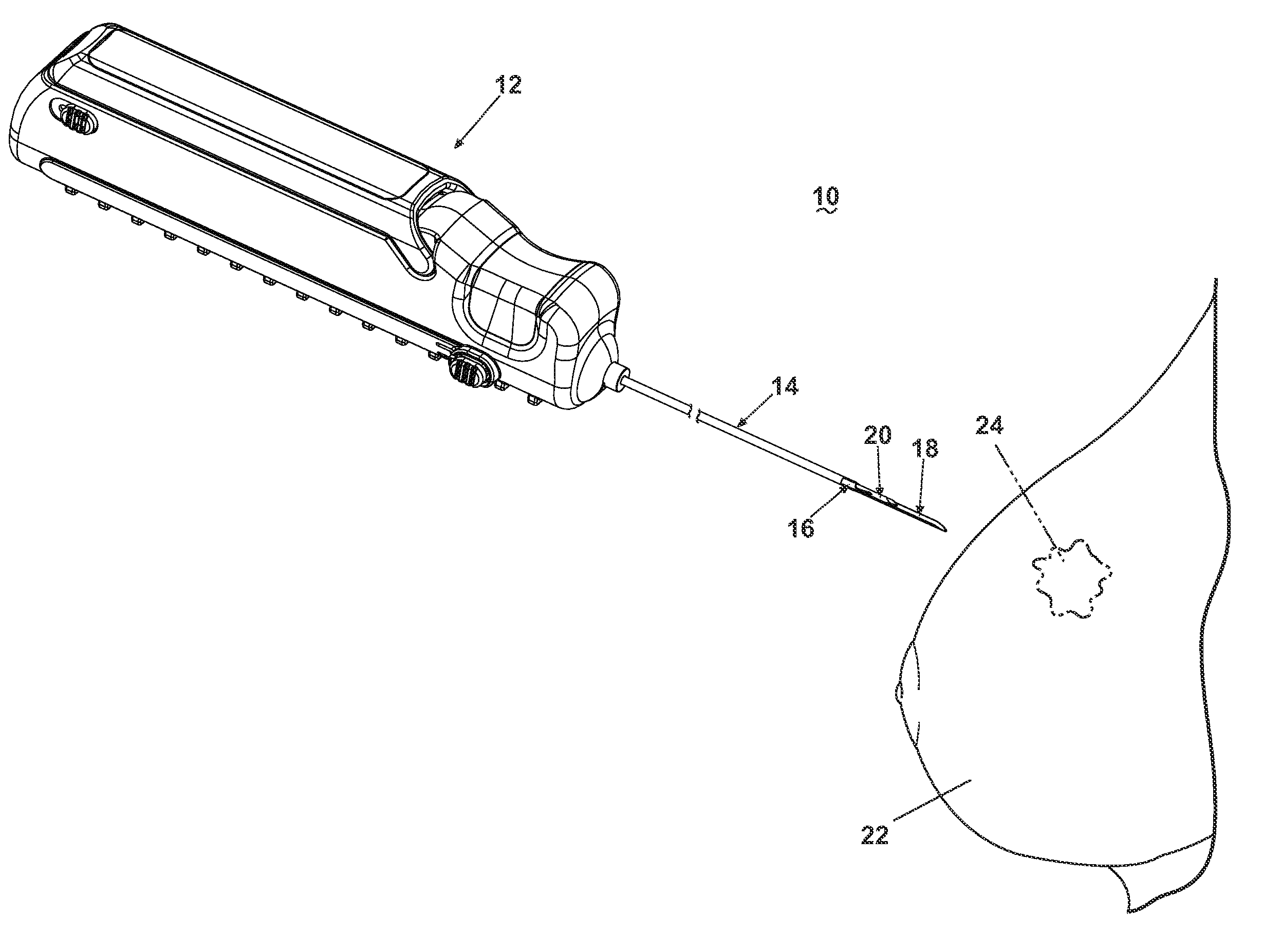
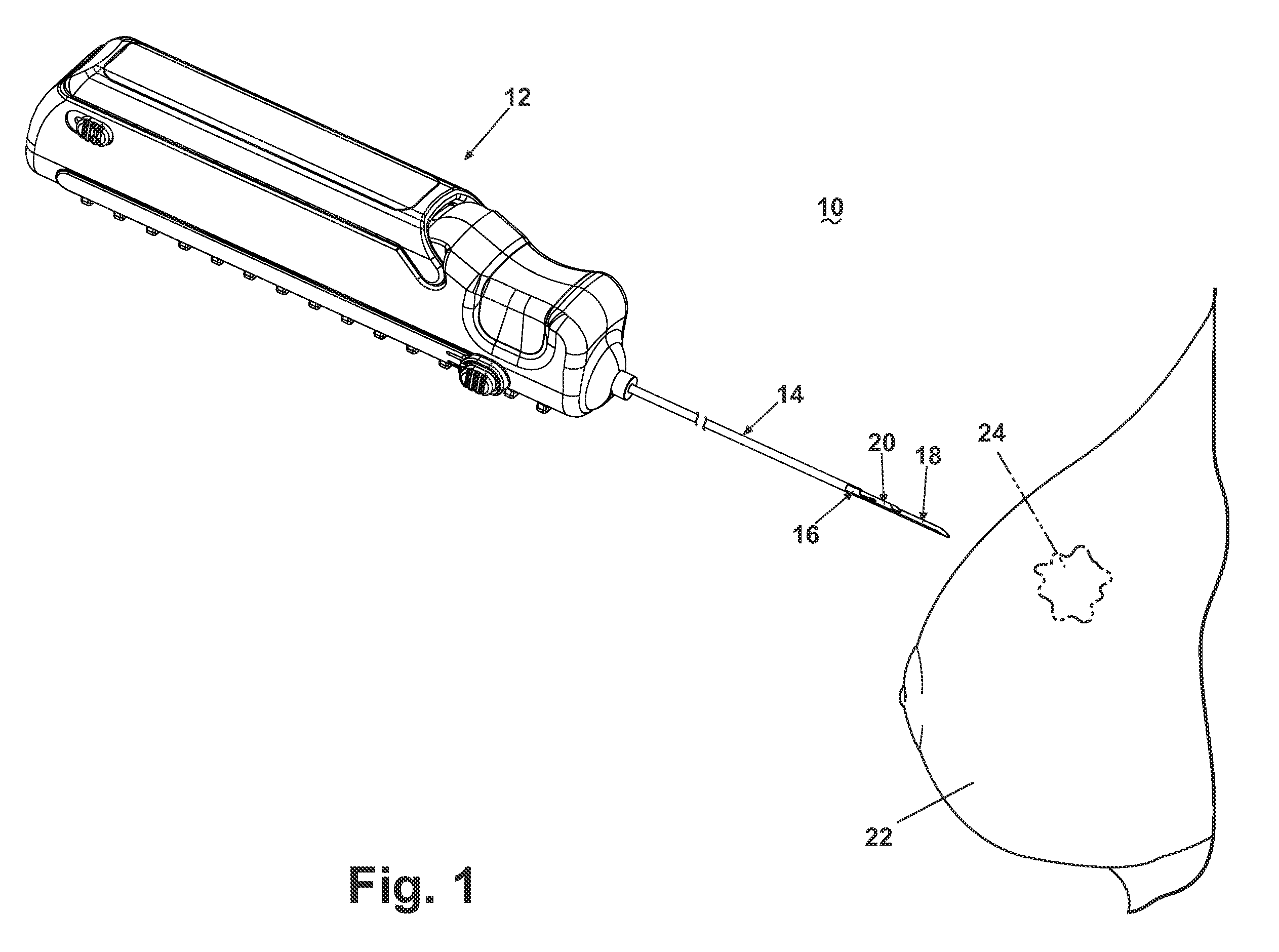
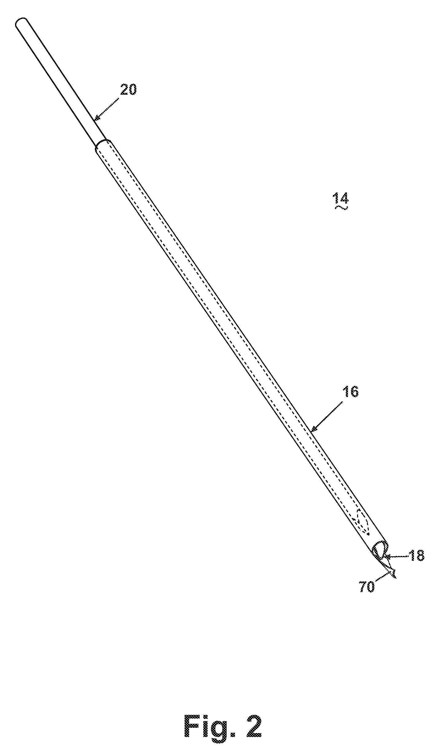
[0025]Referring now to the drawings, and specifically to FIG. 1, a core biopsy device 10 is illustrated comprising an actuator assembly 12 structurally and operably connected to a cannula assembly 14. The cannula assembly 14 is utilized to penetrate a tissue mass 22 for obtaining a core biopsy sample from a lesion 24 as more specifically described hereinafter. An embodiment of the actuator assembly 12 is described and illustrated herein comprising an automated, integrated hand-held device capable of controlling the acquisition and removal of the core biopsy sample from the lesion 24. An actuator assembly 12 is preferably utilized that is capable of automated firing of the cannula assembly 14, with the additional capability of firing a pair of telescoping cannulae and a stylet with one triggering action, or firing an inner cannula and an outer cannula independently. As described and illustrated herein, the actuator assembly 12 is capable of controlled rotation of the outer cannula ar...


PUM


Abstract

A core biopsy device comprises a cutting cannula provided at a distal end with a helical excising blade. The cutting cannula can be rotated within a tissue mass so that the helical excising blade can excise a biopsy sample from the surrounding tissue.

Description

CROSS-REFERENCE TO RELATED APPLICATION(S)[0001]This application is a continuation of U.S. patent application Ser. No. 11 / 939,617, filed Nov. 14, 2007, and a continuation-in-part of U.S. patent application Ser. No. 10 / 908,427, filed May 11, 2005, which claims the benefit of U.S. Provisional Application No. 60 / 521,518, filed May 11, 2004, all of which are incorporated herein by reference in their entirety.BACKGROUND OF THE INVENTION[0002]It is frequently necessary to sample or remove a sample from a suspect tissue for testing. In humans, such a sample removal is particularly useful in diagnosis and treatment of cancerous or pre-cancerous conditions. In the case of suspected cancer, particularly cancer of the breast, early detection and diagnosis is critical to the success of the patient's treatment and recovery.[0003]Various techniques are available to aid in detection and diagnosis, including physical examination and imaging, such as mammography, x-ray, ultrasound, magnetic resonance...

Claims


Application Information

Patent Timeline
Patent Type & Authority Applications(United States)
IPC IPC(8): A61B10/00
CPCA61B10/0266
Inventor PETERS, STEPHEN F.
Owner INRAD
Why Eureka
Try Eureka