Electrosurgical instrument

a surgical instrument and electrosurgical technology, applied in the field of electrosurgical instruments, to achieve the effect of reducing the impedance of electrosurgical output, reducing the formation of char and undesirable thermal damage to tissue margins, and reducing the amount of surgical instruments used

Inactive Publication Date: 2007-10-09
GYRUS MEDICAL LTD
View PDF31 Cites 1293 Cited by
  • Summary
  • Abstract
  • Description
  • Claims
  • Application Information

AI Technical Summary

Benefits of technology

[0045]One advantage of the invention is that immersion of tissue structures, such as skin, in the electrically-conductive fluid, reduces the impedance of the electrosurgical output, such that skin surfaces can be cut, vaporised, contoured (cutaneous thermabrasion) or otherwise thermally modified, whilst minimising char formation and undesirable thermal damage to tissue margins. This is particularly advantageous when debriding wounds or ulcers, and in the treatment of a variety of cutaneous or dermatological disorders. Such disorders include: malignant tumours (whether primarily or secondarily involving the skin); port wine stains; telangiectasia; granulomas; adenomas; haemangioma; pigmented lesions; nevi; hyperplastic, proliferative and inflammatory fibrous papules; rhinophyma; seborrhoeic keratoses; lymphocytoma; angiofibromata; warts; neurofibromas; condylomata; keloid or hypertrophic scar tissue.
[0046]Another advantage of the invention is that the desiccation capability is considerably improved by the immersion of structures in the electrically-conductive fluid, particularly as it applies to simple probe type devices such as hooks. This is a result of several factors. The first of these relates to the fact that tissue surfaces dry out quite quickly during surgical procedures, which increases the impedance of electrical contact with tissues. As desiccation performance is current-driven, the high impedance prevents adequate current delivery, and the output impedance of a desiccate voltage range is exceeded. As a result, the tissue is incompletely desiccated and, if this occurs during desiccation of a blood vessel, the lumen will still be patent and any bleeding will not be controlled. The second of these factors occurs as a result of this high impedance tissue adhering to the surface of the tissue treatment electrode. This compounds the problem, as it further reduces the effectiveness of desiccation. The third is that both these factors are enhanced when the tissue treatment electrode has a small contact surface area, particularly if this electrode is a hook which has been used for cutting, as this leads to carbonisation and pitting of the electrode surface, prior to use as a desiccating instrument. These disadvantages are overcome by use of the present invention. In particular, the improved desiccation performance is useful when sealing venous or thin-walled vascular structures as may be encountered during treatment of haemangioma, varicosities or other vascular anomalies as well as during venous harvesting.
[0047]Yet a further advantage of the present invention is that the irrigation of artificial cavities with an electrically-conductive or physiological solution, such as normal saline, provides a number of benefits. The surfaces of tissues exposed during the procedure are prevented from dehydrating, thereby improving their viability, particularly when the healing process is initiated. Tissue debris, electrosurgical smoke and blood are washed from the operative site so improving visualisation. Such devascularised debris produces tissue reactions which could potentially delay healing, increase post-operative pain associated with inflammatory mediators, and increase the risk of wound infection. The consistency of electrical performance of the invention is improved by immersion of the operative site in an electrically-conductive liquid, whereby the voltage potential required to initiate an arc in vapour is more constant compared to the variable effects of different gaseous environments on arc potential.
[0048]In another aspect, The present invention also provides an electrosurgical instrument for the treatment of tissue in the presence of an electrically-conductive fluid medium, the instrument comprising an instrument shaft, a tissue treatment electrode mounted at the distal end of the shaft, and removal means, the instrument having an apertured portion through which matter can be aspirated by the removal means from the region surrounding the tissue treatment electrode, the removal means comprising a channel formed within the instrument shaft and leading from the apertured portion, wherein the channel is provided with agitation means movable relative thereto.
[0049]The agitation means thus prevents the build-up of sublimation products within the channel.
[0050]The instrument may further comprise drive means for moving the tissue treatment electrode relative to the distal end of the shaft.

Problems solved by technology

Using high power with a monopolar arrangement is also hazardous, due to the tissue heating that occurs at the return plate, which can cause severe skin burns.
There is also the risk of capacitive coupling between the instrument and patient tissues at the entry point into the body cavity.
However, the depth of effect is directly related to the distance between the two electrodes; and, in applications requiring very small electrodes, the inter-electrode spacing becomes very small, thereby limiting tissue effect and the output power.
Spacing the electrodes further apart would often obscure vision of the application site, and would require a modification in surgical technique to ensure direct contact of both electrodes with the tissue.
When either bipolar or monopolar electrosurgery is employed on the skin surface, there is a high risk of excessive thermal damage and tissue carbonisation.
Such thermal damage and carbonisation can lead to delayed healing, wound infection and excessive scar formation.
In addition to these problems, when using bipolar arrangements, the impedance of the electrical contact between the skin and the return electrode can significantly reduce effectiveness.
One of the obvious limitations with the design is that the active electrode (typically a needle) must be completely buried in the tissue to enable the return electrode to complete the circuit.
Another problem is one of the orientation: even a relatively small change in application angle from the ideal perpendicular contact with respect to the tissue surface, will change the contact area ratio, so that a surgical effect can occur in the tissue in contact with the return electrode.
In the course of an operation, veins may be severed, with resultant infusion of the liquid into the circulation, which could cause, among other things, a dilution of serum sodium which can lead to a condition known as water intoxication.
This type of instrument is intended primarily for use in open air or gas-filled environments, and is not suitable for use with electrosurgical procedures which require distension of a body cavity.
However, where the volume of a body cavity is small—for example in arthroscopic surgery where even the large joints, such as the knee, may only accommodate 50-60 ml of irrigation fluid—the following problems may occur, namely:(i) Heated fluid in the immediate vicinity of the tissue contact electrode can cause collateral tissue damage;(ii) The products of the tissue vaporised by the tissue contact electrode can cause visualisation problems; and(iii) Soft tissue present in a joint space tends to move about, making it difficult to apply the active electrode to vaporise such tissue.
Whilst this can be achieved according to this technique; there are two significant performance limitations.
The first of these limitations is that the gaseous products of tissue vaporisation contain fatty products which have a sublimation property, i.e., they condense directly to a solid; sublimation occurring at temperatures well above boiling point.
Thus, if a parallel suction shaft is used, the build up is along its entire length, and eventually completely blocks the tube.
This process, even at the flow rates dictated by minimal influence on the power threshold, can cause very rapid blocking.
Obviously, a larger tube bore would increase the time before blockage, but this occurs so rapidly that the required bore size for a useful electrode life is beyond the dimensions of the maximum shaft diameter.
The problems of sublimation are compounded by aspiration of tissue pieces which are incompletely vaporised before being excised from the remainder of the tissue.
The second of these limitations also relates to adherence of tissue to the tissue contact electrode.
With a static tissue contact electrode, there is an inevitable compromise between these performances variables.

Method used


Image

  • Electrosurgical instrument
  • Electrosurgical instrument
  • Electrosurgical instrument

Examples


first embodiment

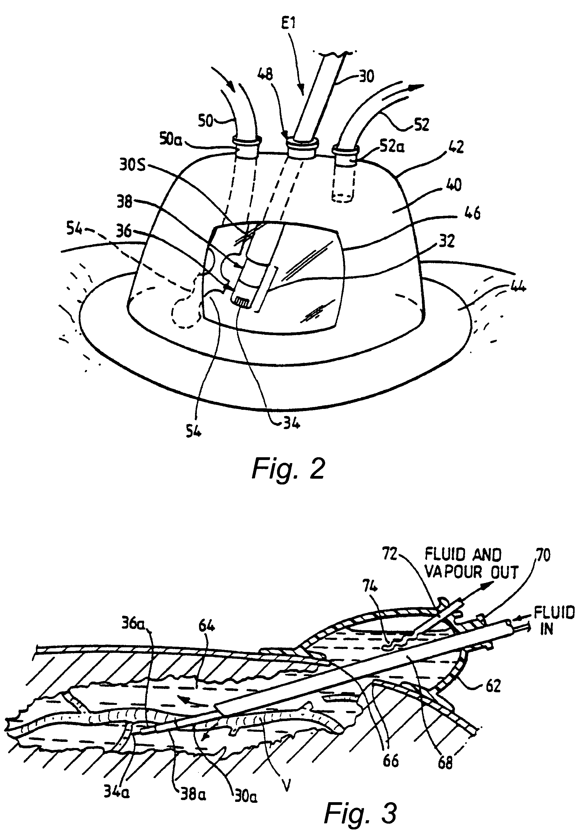
[0098]In a first embodiment, shown in FIG. 2, an electrode unit E1 is detachably fastened to the handpiece 3 (not shown). The electrode unit E1 comprises a shaft 30 which may be a conductive (e.g., metallic) tube covered with an insulating sheath 30S, with an electrode assembly 32 at the distal end of the shaft. At the other end of the shaft 30 (not shown), means are provided for connecting the unit E1 to the handpiece 3 both mechanically and electrically.

[0099]The electrode assembly 32 is bipolar, having an active (tissue treatment electrode) 34 which is axially spaced from a return electrode 38 by means of an insulator 36. The return electrode 38 is constituted by the distal end portion of the tube 30, the portion not being covered by insulating sheet material. In use, the active electrode 32 is positioned in contact with, or in close proximity to, the tissue to be treated. This means that, in normal use when the electrode assembly 32 is immersed in a conductive fluid medium 40, t...

second embodiment

[0104]In a second embodiment, shown in FIG. 3, a fluid enclosure 62 is positioned over a site on the patient's body wherein a space 64 has been surgically created in the tissues through an incision 66. This space 64 may be created using a dissecting instrument under endoscopic visualisation prior to application of the fluid enclosure 62, or may be created under a fluid-filled environment using an electrosurgical instrument or instruments based on the electrode assembly 32, or may be based on a combination of the two. Advantageously, the fluid-filled environment, combined with the generator 1 and instrument system for use with the invention, allows the use of tissue treatment electrodes commonly used for dissection, for example, the hook electrode 34a shown in FIG. 3 or a needle electrode. Such electrodes allow the sealing of larger blood vessels than would normally be treated in this way in a gaseous environment. This is particularly beneficial when sealing, for example a large vein...


PUM


Abstract

A system and method are disclosed for removing a uterus using a fluid enclosure inserted in the peritoneal cavity of a patient so as to enclose the uterus. The fluid enclosure includes a distal open end surrounded by an adjustable loop, that can be tightened, a first proximal opening for inserting an electrosurgical instrument into the fluid enclosure, and a second proximal opening for inserting an endoscope. The loop is either a resilient band extending around the edge of the distal open end or a drawstring type of arrangement that can be tightened and released. The fluid enclosure is partially inserted into the peritoneal cavity of a patient in a deflated condition and then manipulated within the peritoneal cavity over the body and fundus of the uterus to the level of the uterocervical junction. The loop is tightened around the uterocervical junction, after which the enclosure is inflated using a conductive fluid. The loop forms a pressure seal against the uterocervical junction to contain the conductive fluid used to fill the fluid enclosure. Endoscopically inserted into the fluid enclosure is an electrosurgical instrument that is manipulated to vaporize and morcellate the fundus and body of the uterus. The fundus and body tissue that is vaporized and morcellated is then removed from the fluid enclosure through the shaft of the instrument, which includes a hollow interior that is connected to a suction pump The fundus and body are removed after the uterus has been disconnected from the tissue surrounding uterus.

Description

CROSS-REFERENCES TO RELATED APPLICATIONS[0001]The present application is a continuation-in-part of application Ser. No. 10 / 437,431, filed May 14, 2003, now abandoned which is a continuation of application Ser. No. 09 / 462,927, filed Mar. 27, 2000, now U.S. Pat. No. 6,565,560, which is the national phase of International Application PCT / GB98 / 02094, filed Jul. 15, 1998, which designated the U.S., and a continuation-in-part of application Ser. No. 10 / 036,500, filed Jan. 7, 2002, now U.S. Pat. No. 6,923,803 which is a continuation-in-part of application Ser. No. 10 / 024,348, filed Dec. 21, 2001, now abandoned, which is a continuation-in-part of application Ser. No. 09 / 484,225, filed Jan. 18, 2000, now U.S. Pat. No. 6,336,926, the entire contents of which are hereby incorporated by reference in this application.FIELD OF THE INVENTION[0002]The present invention relates to an electrosurgical instrument for the treatment of tissue in the presence of an electrically-conductive fluid medium, to...

Claims


Application Information

Patent Timeline
Patent Type & Authority Patents(United States)
IPC IPC(8): A61B18/18A61B17/34A61B18/00A61B18/14A61B19/00
CPCA61B17/3423A61B18/1482A61B18/1485A61B18/149A61B18/148A61B2218/008A61B19/38A61B2018/00196A61B2018/00208A61B2018/00517A61B2018/00559A61B2018/00601A61B2018/1213A61B2018/1253A61B2018/1472A61B2018/162A61B2018/1861A61B2218/002A61B2218/007A61B90/40
Inventor GOBLE, NIGEL M.
Owner GYRUS MEDICAL LTD
Why Eureka
Try Eureka