Eureka AIR delivers breakthrough ideas for toughest innovation challenges, trusted by R&D personnel around the world.

Radiotherapy apparatus

Inactive Publication Date: 2009-01-15
ELEKTA AB
View PDF8 Cites 30 Cited by
  • Summary
  • Abstract
  • Description
  • Claims
  • Application Information

AI Technical Summary

Benefits of technology

[0008]This requirement is incompatible with enclosed radiotherapy systems, in which the patient is inserted into a cylindrical aperture in the apparatus. Accordingly, the patient support that is provided in combination with such apparatus is generally provided with a relatively large range of motion in the horizontal axis parallel to the cylindrical aperture. This allows the patient to be placed on the couch, positioned accurately (or their position determined accurately), and then transported into the cylindrical aperture by translational movement of the couch. Knowledge of the distance moved by the couch should allow the patient's position inside the treatment apparatus to be inferred.
[0011]The support drive means can be located in the base or in the support, and allows the patient support system as a whole to be translated, thereby permitting the patient to be moved into and out of an enclosed treatment area without affecting the vertical location of the patient. The cantilever section on which the patient is supported maintains the same geometric shape at all times and therefore the positional calibration taken with the patient outside the treatment area remains valid. The only change to the patient position is in the translational position, which can be calibrated by way of fixed end stops for the support drive means.

Problems solved by technology

This requirement is incompatible with enclosed radiotherapy systems, in which the patient is inserted into a cylindrical aperture in the apparatus.
This movement does however introduce an inaccuracy into the patient position.
That will result in a slight downward movement of the patient.
This downward movement will vary with the weight distribution of the patient and will therefore be very difficult to model, predict, and allow for.

Method used


Image

  • Radiotherapy apparatus
  • Radiotherapy apparatus
  • Radiotherapy apparatus

Examples


Embodiment Construction

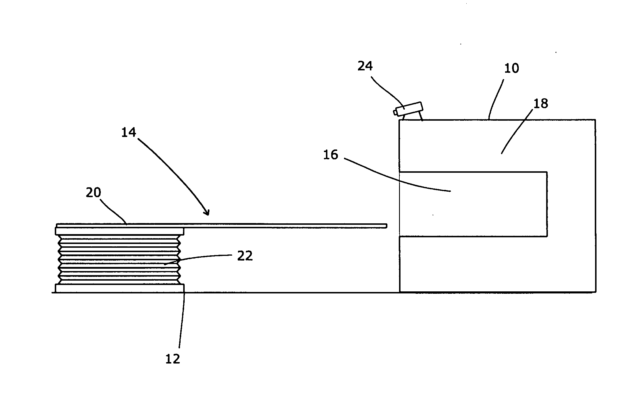
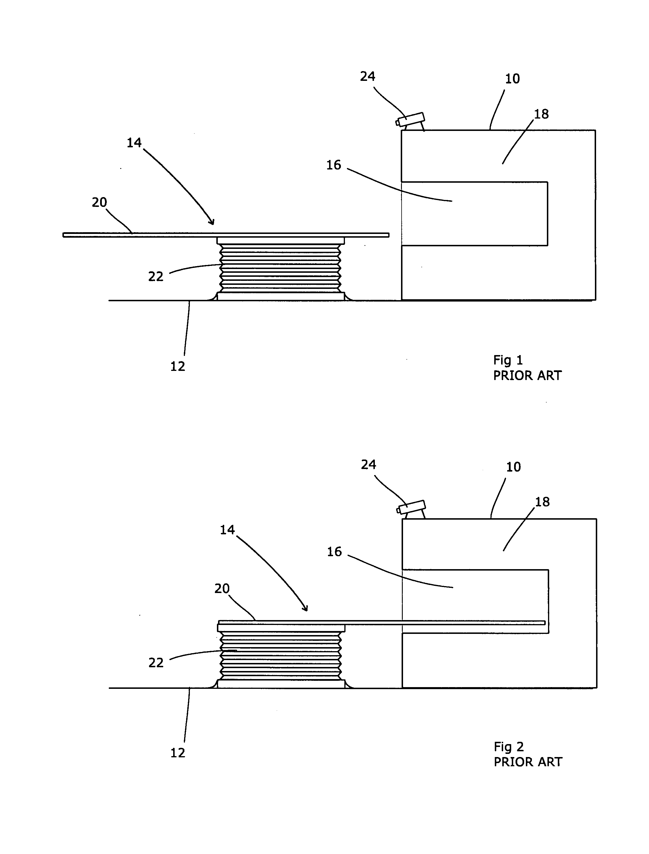
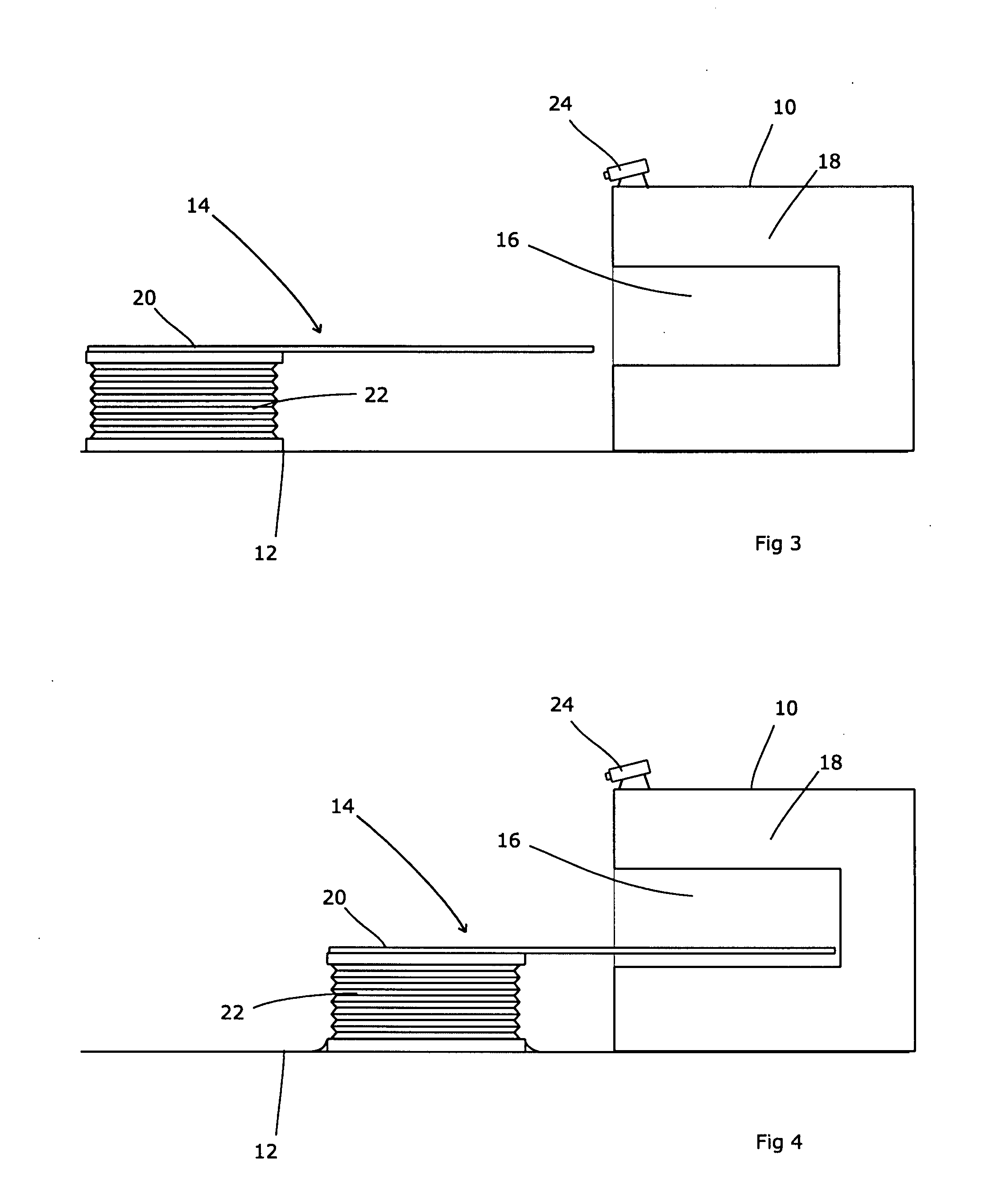
[0025]Referring to FIG. 1, a radiotherapeutic apparatus 10 rests on a floor 12. A patient support 14 is placed in front of the radiotherapy apparatus 10 in order to support a patient during treatment. The radiotherapeutic apparatus 10 is generally of the sort in which a cylindrical hole 16 is provided into which the patient is placed for treatment. A generally annular structure 18 is disposed around the cylindrical aperture 16 and contains the necessary radiation sources etc. which are typically able to move around the cylindrical aperture 16 in order to direction radiation towards the patient from a range of directions. By doing so, the dosage applied to areas around (but not within) the target volume can be minimised whilst maximising the dose delivered to the target volume itself.

[0026]The patient support 14 consists of a generally horizontal couch 20 onto which the patient is placed. This is held in a desired position by an upright support 22 which is servo-controlled so as to l...


PUM


Abstract

A patient support system comprises a base, an upstanding support, and a couch attached to the support and having a cantilever section extendable beyond the support; the support including a couch drive means to adjust the position of the couch relative to the support; further comprising a support drive means for translationally driving the support relative to the base in the direction of the cantilever section. This removes inaccuracies from patient position measurements that result from changes in the cantilever geometry during movement of the patient from a measuring position to a treatment position. The support drive means can be located in the base or in the support, and allows the patient support system as a whole to be translated, thereby permitting the patient to be moved into and out of an enclosed treatment area without affecting the vertical location of the patient. The only change to the patient position is in the translational position, which can be calibrated by way of fixed end stops for the support drive means. The present invention further relates to a radiotherapy apparatus, comprising a patient support as set out above, and an enclosed treatment area positioned in line with the cantilever section.

Description

FIELD OF THE INVENTION[0001]The present invention relates to apparatus for use in radiotherapy.BACKGROUND ART[0002]Radiotherapy operates by directing a beam of harmful radiation towards a cancerous region of a patient. Care is needed both to ensure that the prescribed dose is applied to the tumour and also that a minimum dose is applied to healthy tissue. Inefficiencies in either respect reduce the effectiveness of the treatment; if the prescribed dose is not achieved then the tumour will be more likely to recur, whereas excessive dose outside the tumour will damage healthy tissue, may cause side effects, and may slow the patient's recovery from treatment thereby limiting the rate at which doses can be applied.[0003]Care is therefore taken to shape or modulate the beam so as to limit dose rates outside the tumour and maximise dose rates within the tumour. This clearly requires accurate knowledge of the location and extent of the tumour, which is usually obtained via imaging apparatu...

Claims


Application Information

Patent Timeline
IPC IPC(8): A61N5/00
CPCA61B6/0457A61B6/5276A61N2005/1059A61N2005/105A61N5/1049A61B6/0487
Inventor BOURNE, DUNCAN NEILSTREAMER, RALPHHITCHINGS, ALAN
Owner ELEKTA AB
Why Eureka
Eureka Blog
Learn More