
Electronic lock

a technology of electronic locks and mechanical locks, applied in the field of electronic locks, can solve the problems of strength and security, mechanical locks, moving pins or other mechanical parts, and the complexity and cost of the problem of reducing,

Inactive Publication Date: 2009-01-15
VOOSEN ROBERT C
View PDF8 Cites 42 Cited by
  • Summary
  • Abstract
  • Description
  • Claims
  • Application Information

AI Technical Summary

Benefits of technology

[0009]The present invention transfers the majority of power required to mechanically move the blocking or engaging mechanism directly to the user, incorporating it into the normal action of turning the key. The invention also removes initial load from the electro-mechanical control device so that smaller more power efficient devices can be used within the lock.
[0011]By reducing the load, the invention also allows the use of many alternative electro-mechanical devices that would be unsuitable in traditional mechanisms since it imposes no start up loads and no parasitic loads, and requires very little movement of the control or steering device. Since the load on the device is defined within the mechanism, regardless of outside force applied, unusual approaches to controlling movement, such as electrically changing fluid viscosity, may be incorporated into lock designs providing lower power requirements and / or lower costs.

Problems solved by technology

As the complexity and cost come down electronic locks may well replace mechanical locks in many applications.
The features and value of electronic locks make them more practical and efficient in some industries now but still have issues with strength and security compared to mechanical locks.
Creating a robust electronic lock while keeping it within the outline of a standard mechanical lock type is one challenge and keeping it easy to use is another challenge.
Moving pins or other mechanical parts that have sufficient strength to keep the lock secure or to drive cams or latches within the lock can require considerable relative power.
The size constraints imposed by fitting the electronic and electro-mechanical parts within a standard lock body also impose limitations on the shape and power of the electro-mechanical device.
Smaller devices often either lack the power to move appropriate components or are too costly to allow their use in the majority of applications.
Another consideration is that this mechanism must also be designed in such a way that it cannot be easily defeated by external means such as inertia of the lock induced by moving or striking the lock.
In the case of fixed locks on doors or cabinets this is controlled fairly simply but in portable applications, such as padlocks, preventing this means of defeat can be quite intricate.
These anti-inertia devices often also add to the load requirement of the electro-mechanical device.
The largest effort and use of power in any mechanism is often overcoming the initial momentum of the parts, including the parts of the electro-mechanical device itself.
Solenoids are notoriously inefficient in converting electrical power to mechanical movement.

Method used


Image

  • Electronic lock
  • Electronic lock
  • Electronic lock

Examples


Embodiment Construction

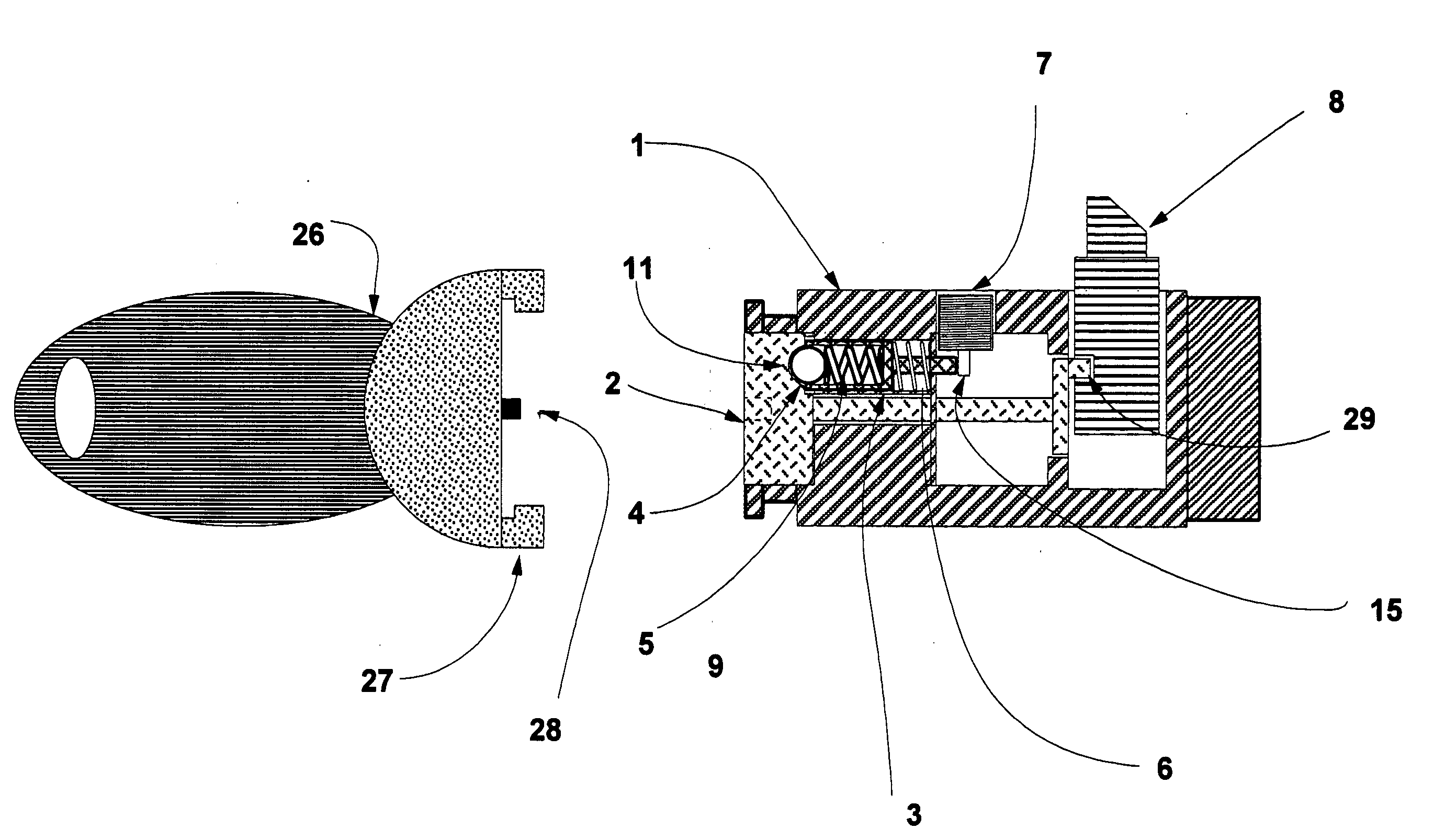
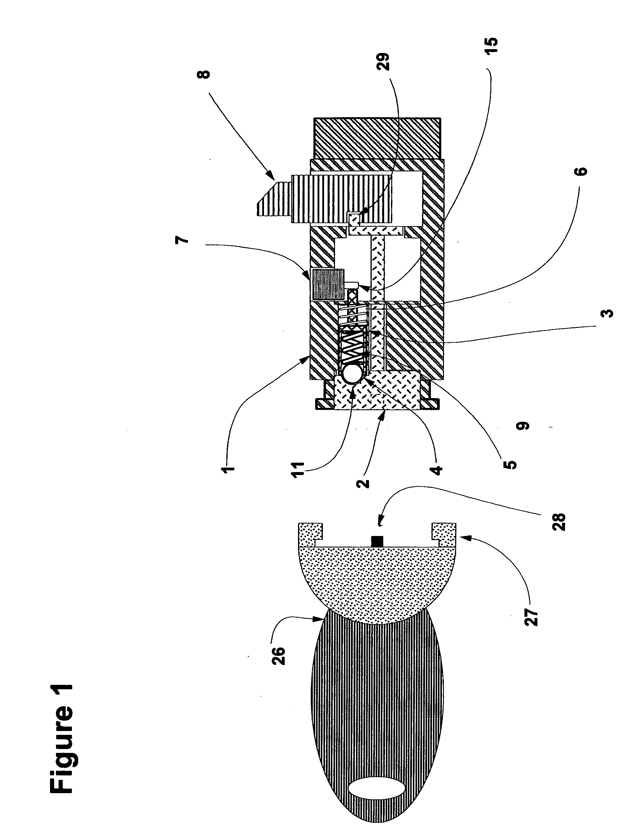
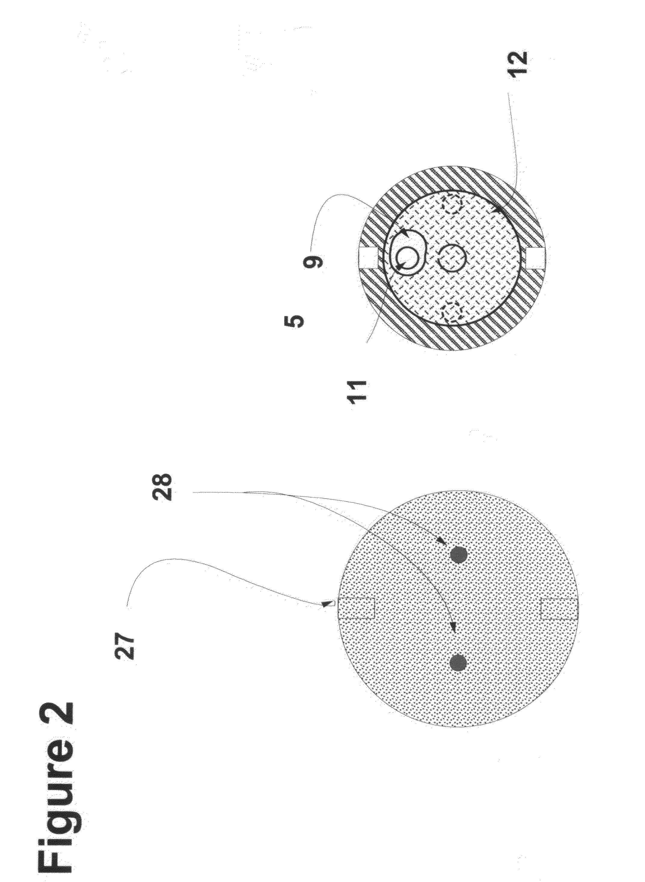
[0026]Referring to FIGS. 1-7, the present invention is an electronic lock generally comprising a lock body (1), a front barrel (2), a locking pin (3), a ball bearing (4), a thrust spring, (5) a return spring (6), a solenoid (7), a latch (8), and a key (26). The front barrel (2) is turned by the key (26) by two drive pins (28) while the key is held on the lock body with a bayonet mechanism (27). The front barrel drives an attached cam (29) that retracts the latch (8) which opens the lock. The locking pin (3) prevents the barrel from turning unless the locking pin moves back and clears the cutout (9) in the back of the barrel (10).

[0027]The end of the locking pin (3) against the back of the barrel (2) is hollow and contains the ball bearing (4) and thrust spring (5). When at rest, the end of the locking pin (3) is positioned in the cutout of the barrel (2) at a depth that will restrict the barrel (2) when turned to the end of the cutout. The ball bearing (4) protrudes from the hollow ...


PUM


Abstract

Disclosed is an electronic lock. In one embodiment, the electronic lock comprises a body, a barrel having a slot, a pin disposed in the slot, a blocking member disposed in the body to prevent movement of the pin, and an electro-mechanical device. Activation of the electro-mechanical device causes the blocking member to be moved clear of the pin and movement of the barrel causes the pin to be moved out of the slot.

Description

CROSS-REFERENCE TO RELATED APPLICATIONS[0001]This applications claims the benefit of and priority to U.S. Provisional Patent Application Ser. No. 60 / 958,805 filed on Jul. 9, 2007, now pending, which is hereby incorporated by reference in its entirety into this specification.BACKGROUND OF THE INVENTION[0002]The present invention relates to electronic versions of mechanical locks. Typically, a key operated lock whereby a key like device is inserted and turned or pushed to operate the lock as if it were a mechanical device. This type of lock is part of a system with electronic apparatus to identify the key and the lock and to provide power for the operation of electro-mechanical mechanisms. The electronic apparatus determines if the key is allowed to open or unlock the lock. It can also be used in a locking mechanism operated by a handle instead of a key but controlled by the electronic apparatus.[0003]Electronic locks are becoming more common. As the complexity and cost come down elec...

Claims


Application Information

Patent Timeline
IPC IPC(8): E05B47/00
CPCE05B15/0093E05B47/0004E05B47/0011E05C1/12E05B51/02E05B2047/0027E05B47/0623Y10T70/7062E05B47/0012
Inventor VOOSEN, ROBERT C.
Owner VOOSEN ROBERT C
Learn More