Material property measurements using multiple frequency atomic force microscopy

a technology of atomic force microscopy and material properties, applied in the direction of mechanical roughness/irregularity measurement, measurement devices, instruments, etc., can solve the problem of requiring costly and difficult manufacturing of special cantilevers, affecting the accuracy of measurement results, etc. problem, to achieve the effect of higher vibrational modes

Active Publication Date: 2009-01-15
OXFORD INSTR ASYLUM RES INC +1
View PDF31 Cites 26 Cited by
  • Summary
  • Abstract
  • Description
  • Claims
  • Application Information

AI Technical Summary

Problems solved by technology

This approach is has the disadvantage of requiring costly and difficult to manufacture special cantilevers.
A well-known shortcoming of force modulation and other contact mode techniques is that the while the contact forces may be controlled well, other factors affecting the measurement may render it ill-defined.
This in turn means that the change in resonance while maintaining a contact mode feedback loop, which may be called the contact resonance, is ill-defined.
This problem has resulted in prior art techniques avoiding operation at or near resonance.

Method used


Image

  • Material property measurements using multiple frequency atomic force microscopy
  • Material property measurements using multiple frequency atomic force microscopy
  • Material property measurements using multiple frequency atomic force microscopy

Examples


Embodiment Construction

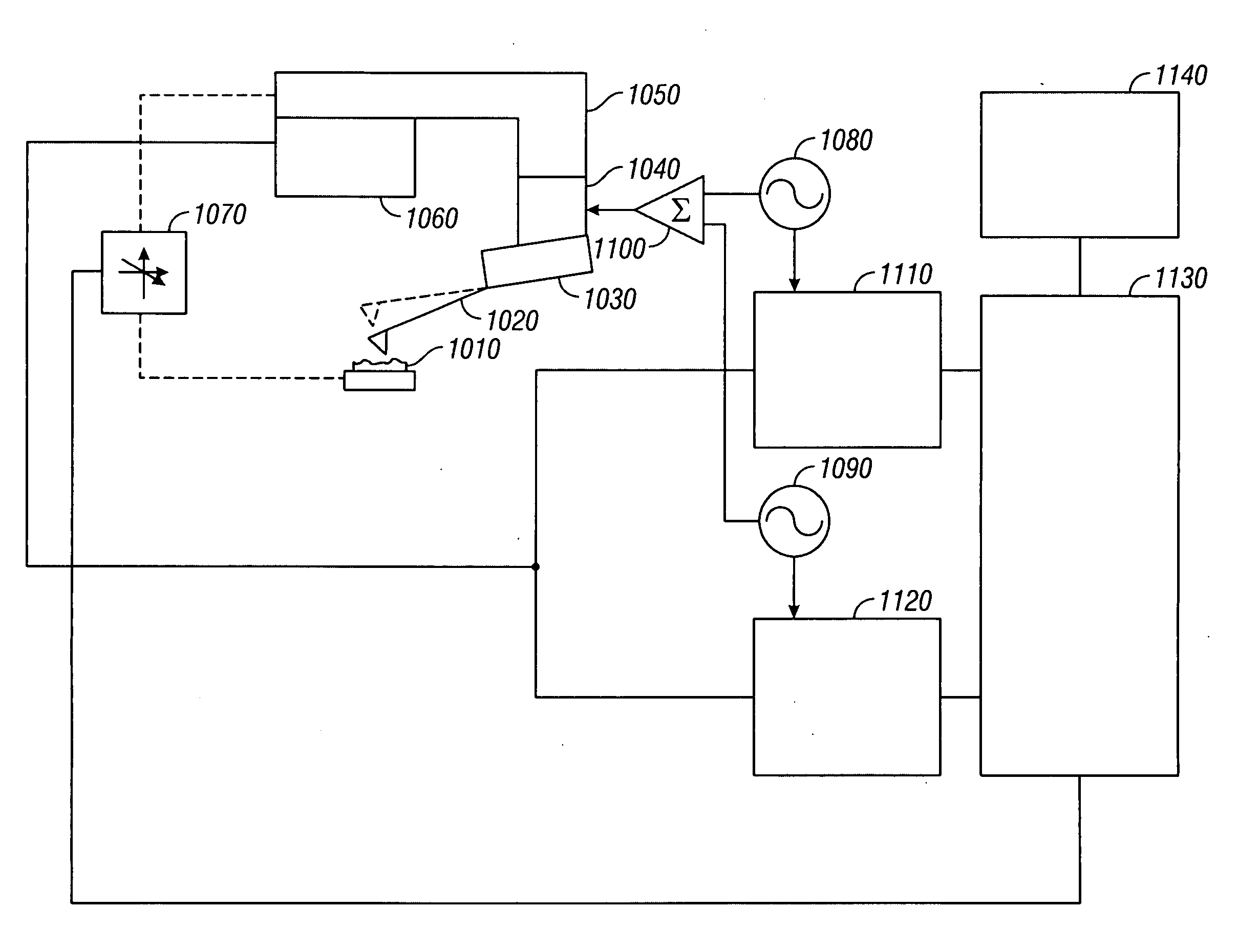
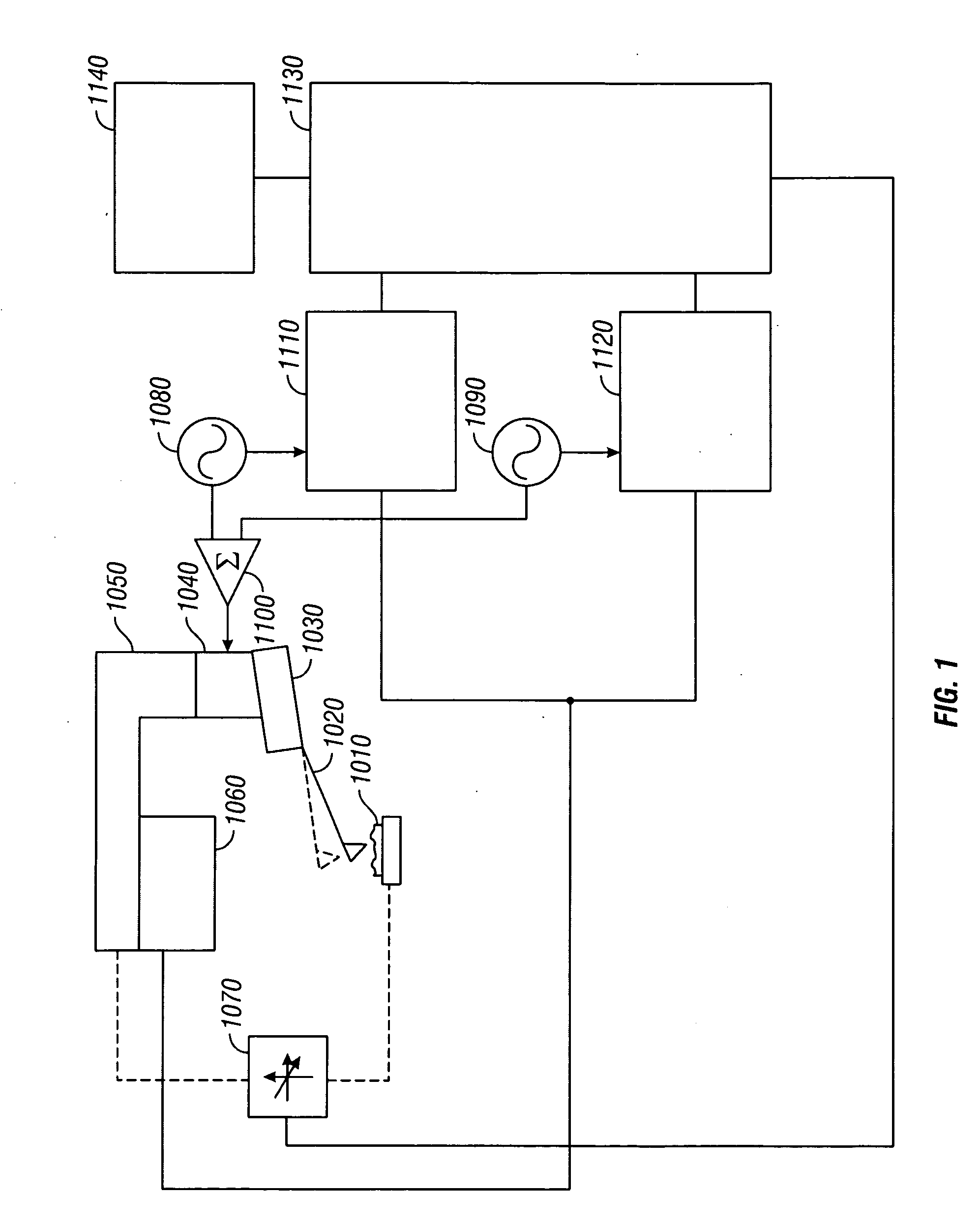
[0125]FIG. 1 is a block diagram of a preferred embodiment of an apparatus for probing multiple eigenmodes of a cantilever in accordance with the present invention. The sample 1010 is positioned below the cantilever probe 1020. The chip of the cantilever probe 1030 is driven by a mechanical actuator 1040, preferably a piezoelectric actuator, but other methods to induce cantilever motion known to those versed in the art could also be used. The motion of the cantilever probe 1020 relative to the frame of the microscope 1050 is measured with a detector 1060, which could be an optical lever or another method known to those versed in the art. The cantilever chip 1030 is moved relative to the sample 1010 by a scanning apparatus 1070, preferably a piezo / flexure combination, but other methods known to those versed in the art could also be used.

[0126]The motion imparted to the cantilever chip 1030 by actuator 1040 is controlled by excitation electronics that include at least two frequency syn...


PUM


Abstract

Apparatus and techniques for extracting information carried in higher eigenmodes or harmonics of an oscillating cantilever or other oscillating sensors in atomic force microscopy and related MEMs work are described. Similar apparatus and techniques for extracting information using contact resonance with multiple excitation signals are also described.

Description

REFERENCES CITEDU.S. Patent Documents[0001]RE36488 January 2000 Minne et al.[0002]RE36488 January 2000 Elings et al.[0003]Re. 33937 May, 1995 Schubert[0004]U.S. Pat. No. 5,444,244 August 1995 Kirk et al.[0005]U.S. Pat. No. 5,477,732 December 1995 Yasue et al.[0006]U.S. Pat. No. 5,483,822 January 2001 Albrecht et al.[0007]U.S. Pat. No. 5,503,010 April 1996 Yamanaka[0008]U.S. Pat. No. 5,519,212 May 1995 Elings et al.[0009]U.S. Pat. No. 5,519,212 May 1996 Bayer et al.[0010]U.S. Pat. No. 5,646,339 July 1997 Bayer et al.[0011]U.S. Pat. No. 5,646,339 July 1997 Minne et al.[0012]U.S. Pat. No. 5,742,377 April 1998 Han et al.[0013]U.S. Pat. No. 5,742,377 April 1998 Minne et al.[0014]U.S. Pat. No. 5,763,768 June 1996 Henderson et al.[0015]U.S. Pat. No. 5,804,708 September 1998 Yamanaka et al.[0016]U.S. Pat. No. 5,866,805 February 1999 Muramatsu et al.[0017]U.S. Pat. No. 5,866,805 February 1999 Han et al.[0018]U.S. Pat. No. 5,877,412 March 1999 Minne et al.[0019]U.S. Pat. No. 5,883,705 March 1...

Claims


Application Information

Patent Timeline
Patent Type & Authority Applications(United States)
IPC IPC(8): G12B21/08G01Q60/32
CPCB82Y35/00G01Q60/24G01Q60/32G01Q20/00
Inventor PROKSCH, ROGERCALLAHAN, ROGER C.
Owner OXFORD INSTR ASYLUM RES INC
Why Eureka
Try Eureka