Device for detecting roundness of arc of tool tip of diamond tool with arc edge

A diamond tool and detection device technology, applied in the direction of measuring devices, optical devices, instruments, etc., can solve the problems of low detection accuracy and inability to meet the requirements of high-precision tool tip arc roundness measurement, so as to improve detection accuracy, The effect of high-precision detection

Inactive Publication Date: 2010-03-03
HARBIN INST OF TECH
View PDF0 Cites 25 Cited by
  • Summary
  • Abstract
  • Description
  • Claims
  • Application Information

AI Technical Summary

Problems solved by technology

[0016] The purpose of the present invention is to solve the problem that the current method and device used for detecting the roundness of the arc of the diamond tool tip have low detection accuracy and cannot meet the requirements for measuring the roundness of the tip of the arc with high precision. A detection device for circular arc roundness of arc edge diamond tool tip

Method used


Image

  • Device for detecting roundness of arc of tool tip of diamond tool with arc edge
  • Device for detecting roundness of arc of tool tip of diamond tool with arc edge
  • Device for detecting roundness of arc of tool tip of diamond tool with arc edge

Examples


specific Embodiment approach 1

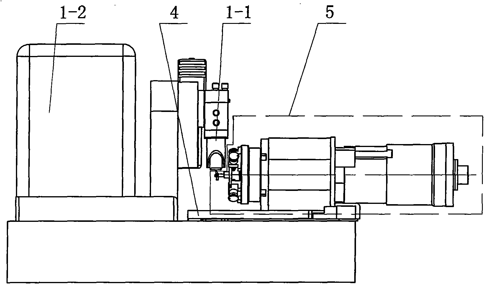
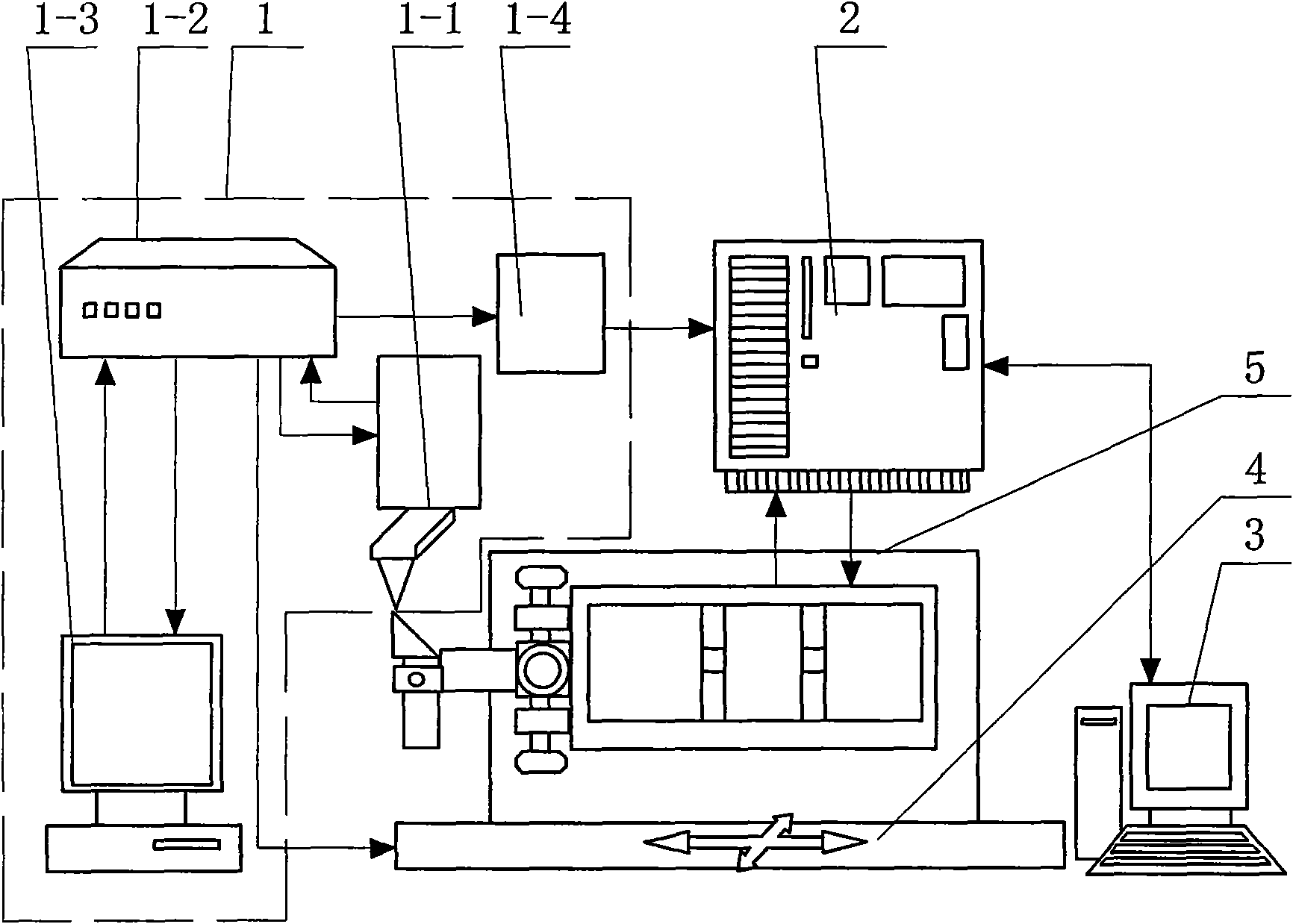
[0026] Specific implementation mode one: the following combination Figure 1-Figure 3 To illustrate this embodiment, this embodiment is composed of an atomic force microscope system 1, a single-chip controller 2, a measurement control computer 3, a two-dimensional precision displacement table 4 and a rotary shaft system 5, and the rotary shaft system 5 is placed in a two-dimensional precision displacement work on stage 4;

[0027]The detection result output end of the atomic force microscope system 1 is connected to the detection result input end of the single-chip controller 2, the single-chip controller 2 is connected to the RS232 interface of the measurement control computer 3 through the RS232 interface, and the control signal output end of the single-chip controller 2 is connected to the rotary shaft system 5 The control signal input terminal of the rotary shaft system 5 is connected to the angular position signal input terminal of the microcontroller controller 2; the di...

specific Embodiment approach 2

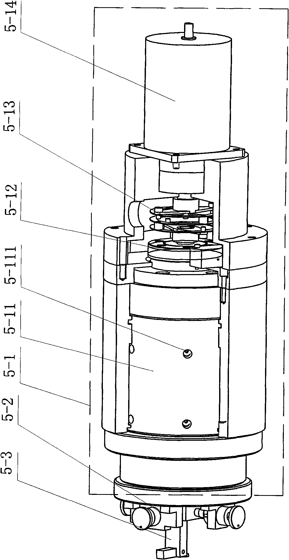
[0040] Specific implementation mode two: the following combination Figure 4 To illustrate this embodiment, the difference between this embodiment and Embodiment 1 is that the centering device 5-2 consists of a bottom disc 5-21, four positioning jackscrews 5-22, and four jacking screw seats 5 -23 and fixture holder 5-24 are formed,

[0041] The upper center of the bottom disc 5-21 is provided with a fixture fixing seat 5-24, and four jacking wire seats 5-23 are fixed on the bottom disc 5-21, and the four jacking thread seats 5-23 are fixed by the fixture fixing seat. 5-24 is the center and evenly distributed on the bottom disc 5-21, and one end of each position-adjusting top wire 5-22 passes through a top wire seat 5-23 and contacts the side wall of the clamp holder 5-24, and the opposite The central axes of the two position-adjusting jackscrews 5-22 are coincident, and the position-adjusting jacking screws 5-22 are threadedly connected with the jacking screw seat 5-23.

[0...

specific Embodiment approach 3

[0045] Embodiment 3: The difference between this embodiment and Embodiment 1 or 2 is that six throttle holes 5-111 are evenly distributed in double rows on the outer surface of the aerostatic bearing 5-11. Other compositions and connections are the same as those in the first or second embodiment.


PUM


Abstract

The invention relates to a device for detecting the roundness of an arc of a tool tip of a diamond tool with an arc edge, which belongs to the technical field of the detection of the roundness of thearc of the tool tip of the diamond tool. The device can solve the problem that the existing device for detecting the roundness of the arc of the tool tip of the diamond tool with the arc edge has theshortcomings of low detection precision and inability of meeting the requirement for the high-precision measurement of the roundness of the arc of the tool tip. The device consists of an atomic forcemicroscopy system, a single-chip microcomputer controller, a measurement control computer, a two-dimensional precision displacement workbench and a rotary shaft system, wherein the rotary shaft systemis arranged on the two-dimensional precision displacement workbench, the measurement control computer is used for displaying detection data and outputting a control signal to the single-chip microcomputer controller for controlling the rotation of the rotary shaft system, the relative position of the rotary shaft system and a scanning probe of the atomic force microscopy system is regulated through the two-dimensional precision displacement workbench, and the signal detected by the scanning probe is transferred from the controller in the atomic force microscopy system to the control computerfor monitoring. The device is used for detecting the roundness of the arc of the tool tip of the diamond tool.

Description

technical field [0001] The invention relates to a detection device for the roundness of the arc of the tip of a diamond tool with an arc edge. Background technique [0002] Ultra-precision machining technology is a manufacturing technology developed specifically for the needs of modern technology in the 1960s. It is a new mechanical processing technology that challenges the high-precision limit of traditional processing methods. As a basic technology in the high-tech field, it integrates cutting-edge technologies in the fields of electronics, sensing, optics, control and measurement. With the application and popularization of ultra-precision machining technology, machining accuracy has increased by 1 to 3 orders of magnitude in a few decades, and it is developing towards higher precision nanometer precision. Japan, the United States, the United Kingdom, Germany Industrialized countries such as China and Russia have included ultra-precision processing and nano-processing tec...

Claims


Application Information

Patent Timeline
Patent Type & Authority Applications(China)
IPC IPC(8): G01B21/20G01B11/26
Inventor 李增强孙涛赵学森宗文俊
Owner HARBIN INST OF TECH
Why Eureka
Try Eureka