
Eureka
For R&D, Eureka makes reading and utilizing patents & technical documents easy.
Eureka AIR
Designed for self-driven R&D workflows. Generate viable solutions, solve complex R&D challenges, empower your innovation with AI.

Eureka Materials
Designed for material experts only. Revolutionize your material R&D, from search, analyze, to developing new materials.

TechResearch
Generate reliable direction feasibility study reports for your R&D in just a few steps.

TechSeek
Discover and master advanced knowledge NOW. Basics, ideas, possibilities, all at once.

TechMind
As an expert in R&D Theories, TechMind can generates customized viable solutions instantly.

TechRisk
Analyze your overall solution with one click, know your potential R&D risks in advance.

TechMonitor
Get weekly tech updates, stay abreast of the latest tech innovations and key insights.
In-Line Valve Sampling System
- Summary
- Abstract
- Description
- Claims
- Application Information
AI Technical Summary
Benefits of technology
Problems solved by technology
Method used
Image

Examples
Embodiment Construction
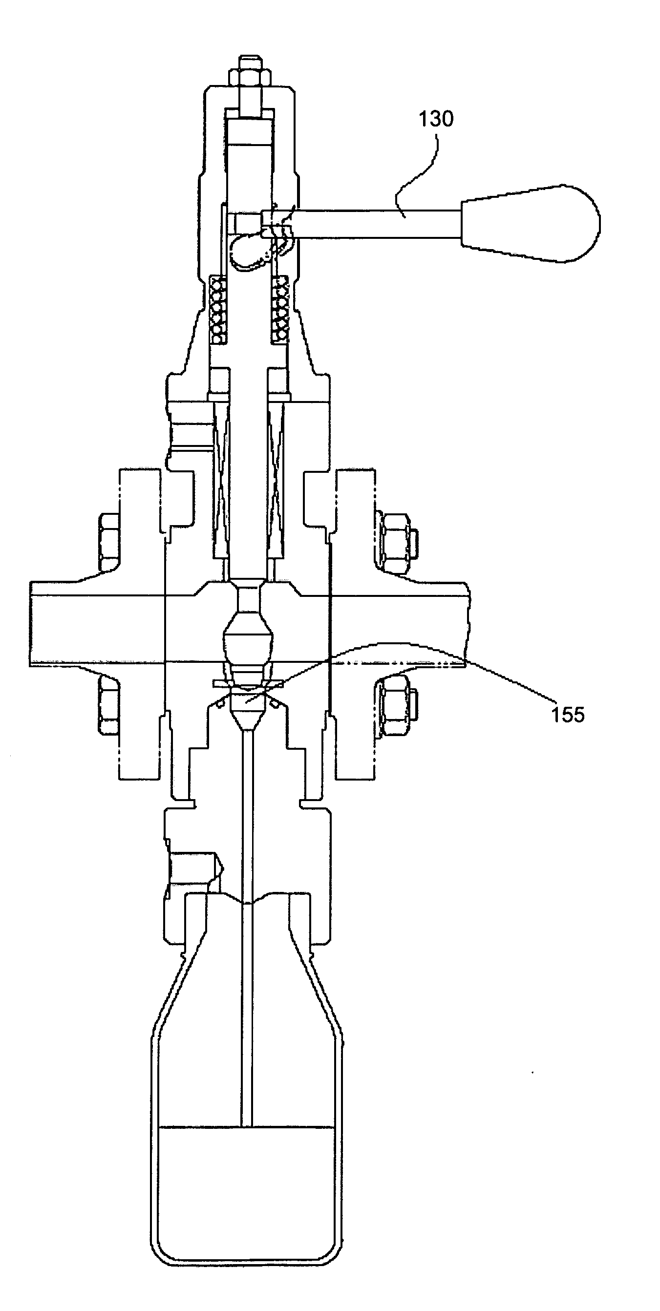
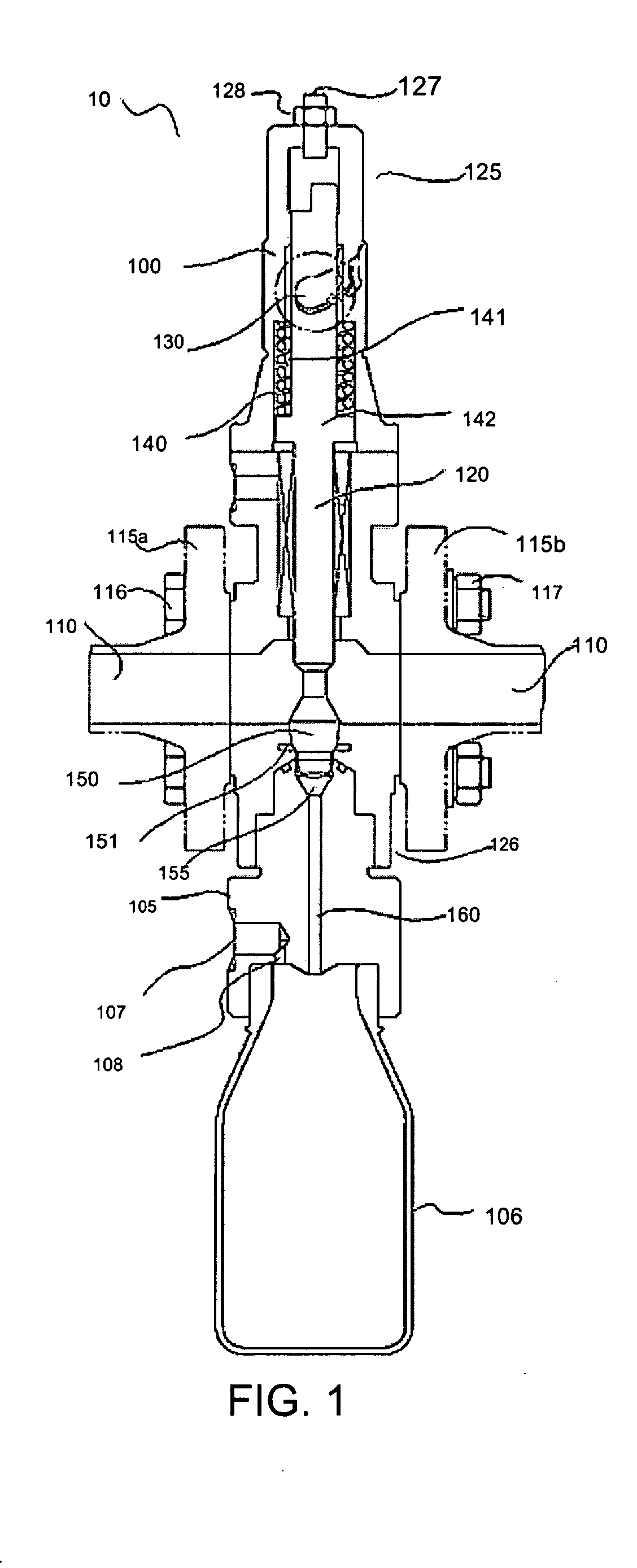
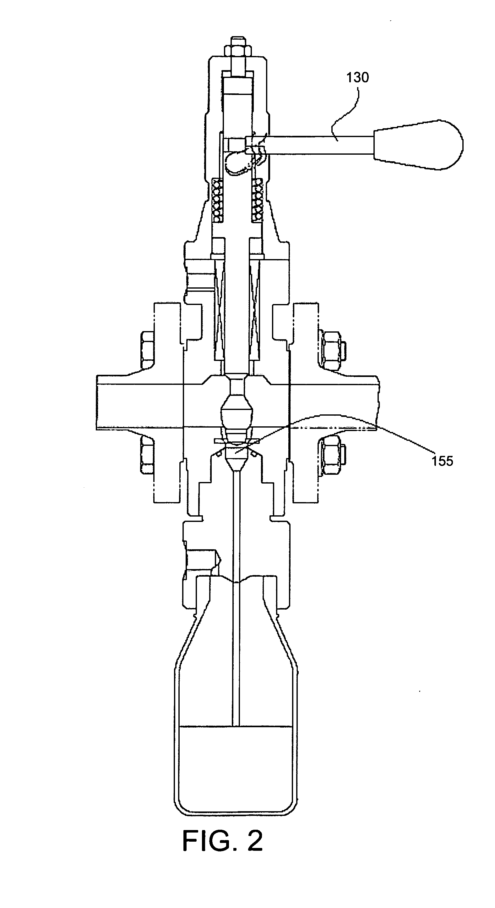
[0014]FIG. 1 illustrates an exemplary embodiment of a sampling system 10 having a valve unit body 100 and a receiving or sampling unit 105 installed directly into a process pipeline 110. Sampling system 10 may be attached to pipeline 110 via valve flanges 115a and 115b. Valve flanges 115a and 115b are the type typically used in valve conduit connections having a plurality of bolts or connectors 116 and retaining nuts 117 spaced around the circumference of flanges 115a and 115b. Valve body 100 includes set screw 127 and hex nut 128 and is positioned along the process flow axis of process pipeline 110. Sampling unit 105 may include, for example, a receptacle or bottle 106 for receiving the sample which is detachably connected from valve unit body 100. Sampling unit 105 also includes a vent 107 for discharging air from bottle 106 when the bottle is filled. Bottle 106 may be, for example standard Glass, PFA or stainless steel with an ISO GL 45 thread to vent 107 via a ¼ inch NPT connect...
PUM
 Abstract
Description
Claims
Application Information
 - R&D Engineer
- R&D Manager
- IP Professional
- Industry Leading Data Capabilities
- Powerful AI technology
- Patent DNA Extraction
Browse by: Latest US Patents, China's latest patents, Technical Efficacy Thesaurus, Application Domain, Technology Topic, Popular Technical Reports.
© 2024 PatSnap. All rights reserved.Legal|Privacy policy|Modern Slavery Act Transparency Statement|Sitemap|About US| Contact US: help@patsnap.com