Method and architecture for reduction in vehicle wiring

a technology for vehicle wiring and architecture, applied in the direction of dc source parallel operation, electric devices, transportation and packaging, etc., can solve the problems of reducing the benefits of modern aircraft affecting the efficiency of electrical power distribution systems, and still affecting the wiring weight of panels

Inactive Publication Date: 2009-01-15
HONEYWELL INT INC
View PDF11 Cites 40 Cited by
  • Summary
  • Abstract
  • Description
  • Claims
  • Application Information

AI Technical Summary

Problems solved by technology

For this reason, cabling from the primary low voltage panels to remote secondary panels still account for a large wiring weight.
Furthermore, these relatively large secondary feeders introduce new installation provision needs and routing problems, which diminish the benefits of modern aircraft electrical power distribution systems.
One drawback of the non-centralized secondary power distribution architecture of FIG. 2 is the associated weight of power feeders (016A, 016B, 017A, 017B) that connect many secondary power distribution boxes (1300A, 1300B, 1300C, 1300D, 1300E, 1300F) to centralized primary power distribution equipment (panels 1200A and 1200B).
The large number of power feeders connecting the centralized power distribution equipment t

Method used


Image

  • Method and architecture for reduction in vehicle wiring
  • Method and architecture for reduction in vehicle wiring
  • Method and architecture for reduction in vehicle wiring

Examples


Embodiment Construction

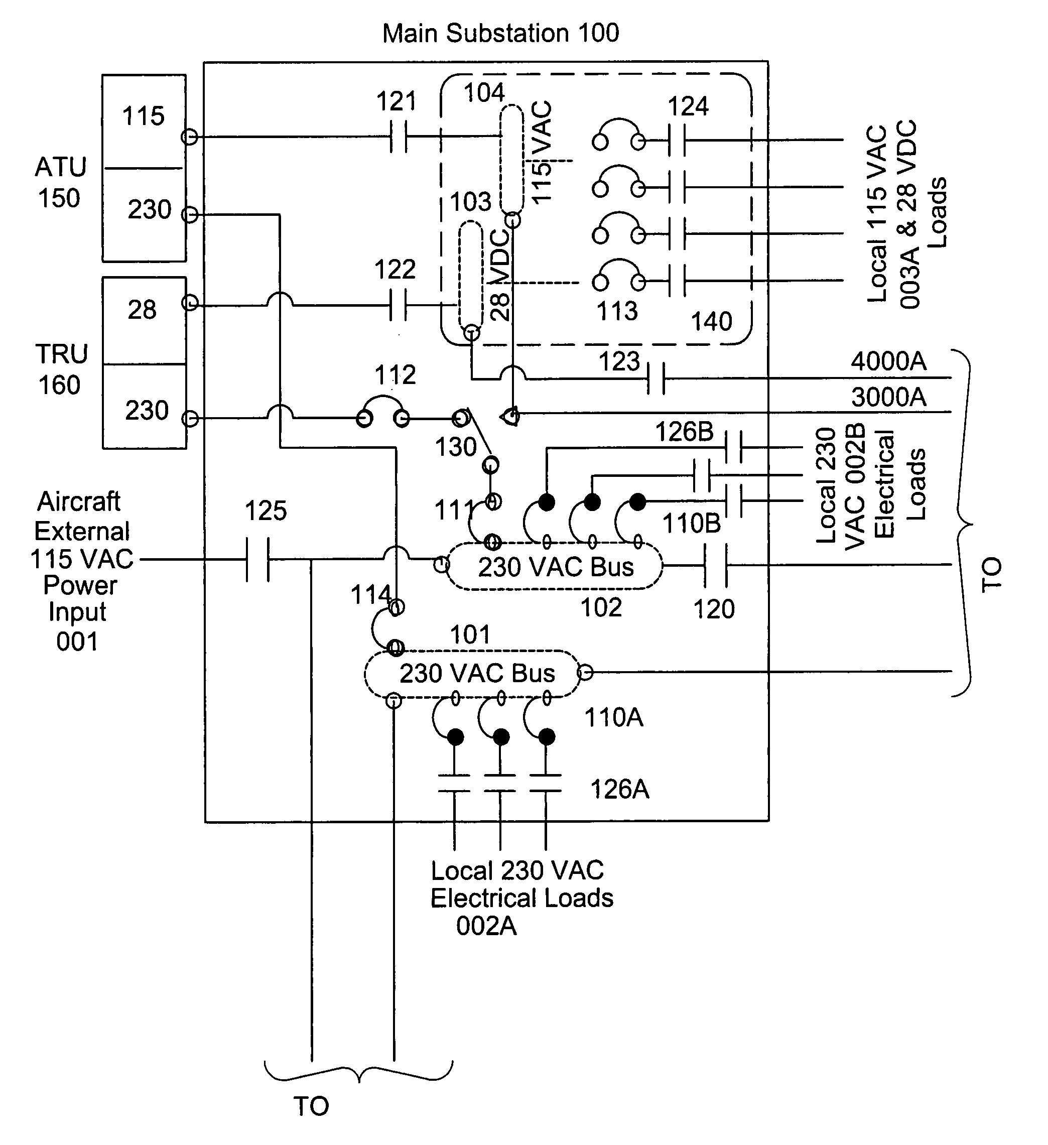
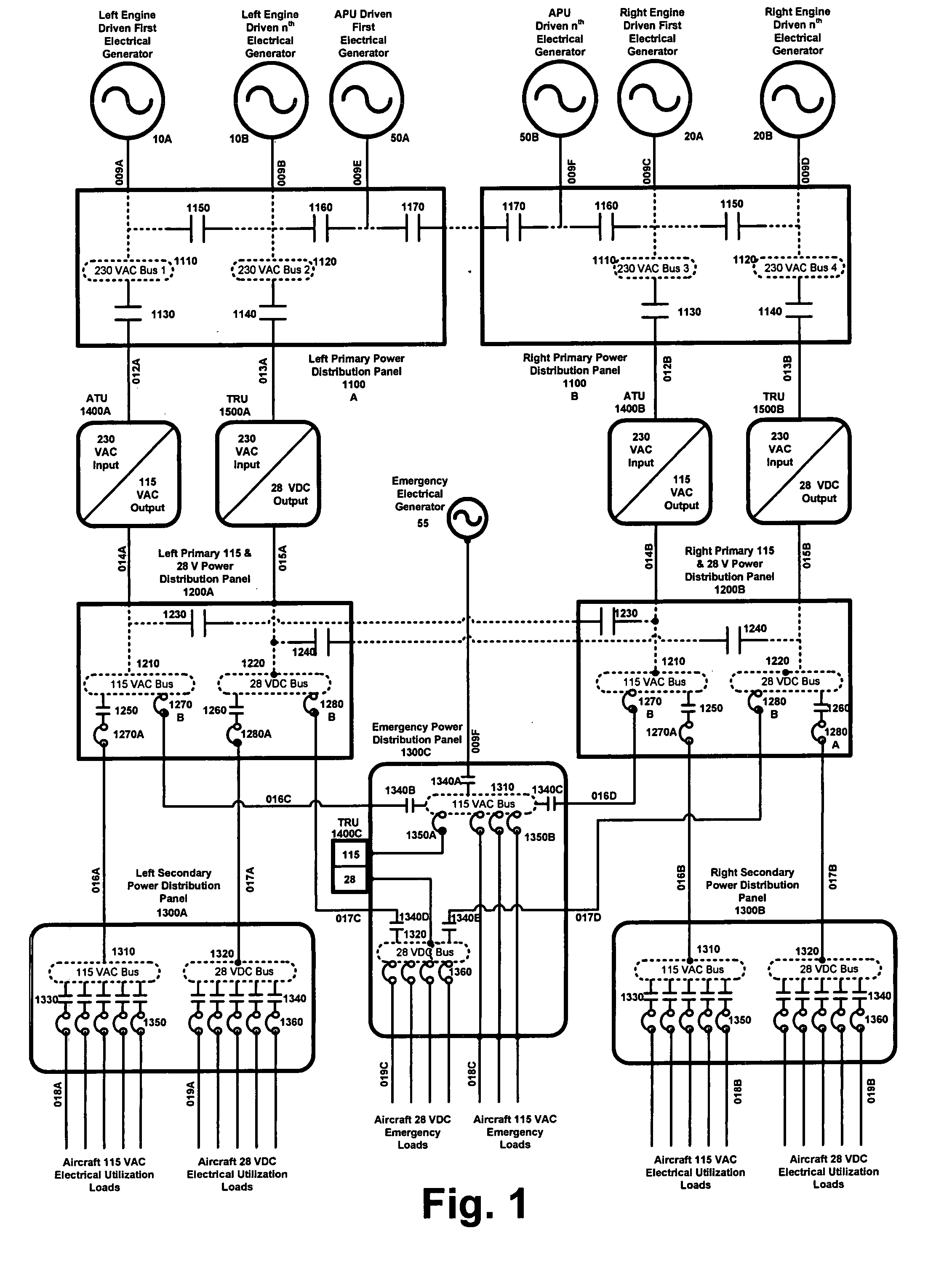
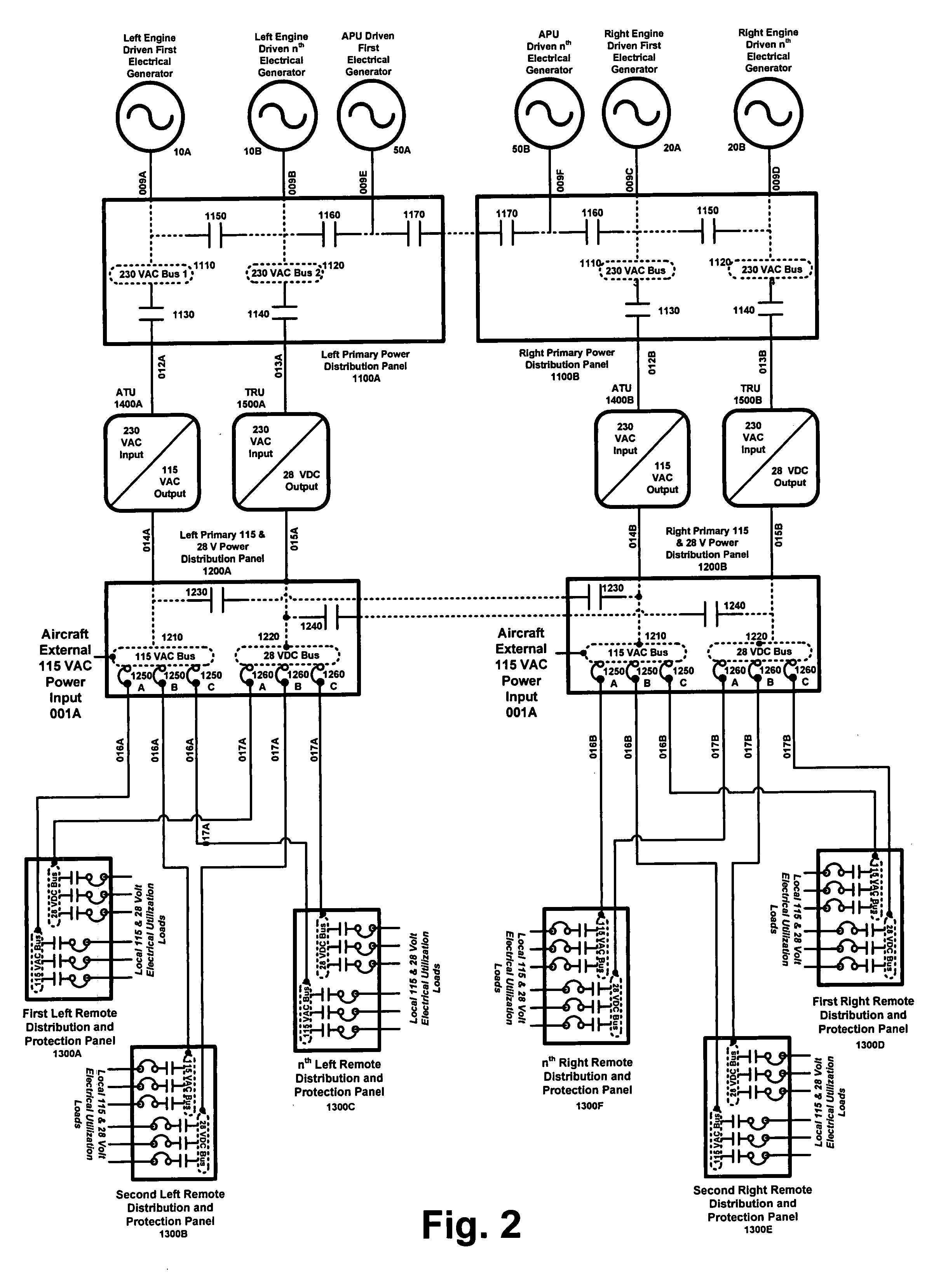
[0027]Aspects of the invention are more specifically set forth in the accompanying description with reference to the appended figures. FIG. 3 is a diagram of an architecture that reduces vehicle wiring by using high voltage primary power and distributed low voltage conversion equipment to feed secondary power boxes, according to an embodiment of the present invention. The architecture in FIG. 3 is modular, and is presented in a ring structure. The architecture provides a high level of integration between distinct levels of power distribution within each modularly arranged distribution panel.

[0028]Due to its large size, the diagram of FIG. 3 is split into 10 portions, which are labeled as FIGS. 3A, 3B, 3C, 3D, 3E, 3F, 3G, 3H, 3I, and 3J. FIGS. 3A-3J connect to each other as shown on the connection map of FIG. 3, and as indicated in each of FIGS. 3A-3J.

[0029]The term “substation” as used in the present description refers generally to the modules that form the architecture system. The ...


PUM


Abstract

Systems and methods perform power conversion and distribution. A system for power conversion and distribution, according to one embodiment comprises: a first generator substation (70) receiving power from a first electrical generator (10); a first main substation (100) for distributing converted power to at least one load, said load being local to the first main substation (100); a ring bus including ring bus feeders (1000, 2000); and at least one satellite substation (700) for powering a remote load, wherein the ring bus feeders (1000, 2000) connect the first generator substation (70) and the first main substation (100) in a ring arrangement, and the at least one satellite substation (700) receives power from the ring bus through a branch substation (500).

Description

BACKGROUND OF THE INVENTION[0001]1. Field of the Invention[0002]The present invention relates to electrical systems for vehicles, and more particularly to a method and architecture for reduction of vehicle wiring through incorporation of modular power distribution panels providing primary and secondary distribution functions in a ring arrangement, and for implementation of point of use conversion devices to provide appropriate electrical power type and quality.[0003]2. Description of the Related Art[0004]A typical / conventional vehicle electrical distribution system is shown in FIG. 1. The electrical distribution system illustrated in FIG. 1 obtains power from various electrical power sources (10A, 10B, 20A, 20B, 50A and 50B) and distributes the power to various vehicle utilization systems and associated loads. Power supply systems 10A, 10B, 20A, 20B, 50A and 50B are exemplary generators, as illustrated in FIG. 1. Systems 10A, 10B, 20A, 20B, 50A and 50B may also be, or may include as...

Claims


Application Information

Patent Timeline
IPC IPC(8): H02J3/04B64D35/08H02J3/38H02G3/02H02J1/10
CPCH02J5/00
Inventor MICHALKO, RODNEY G.
Owner HONEYWELL INT INC
Why Eureka
Try Eureka