Method for regulating a voltage and circuit therefor

a voltage and circuit technology, applied in the field of power supplies, can solve the problems of low output voltage, slowness of pfc systems, and degradation of the dynamic performance of pfc systems,

Active Publication Date: 2009-01-15
SEMICON COMPONENTS IND LLC
View PDF6 Cites 32 Cited by
  • Summary
  • Abstract
  • Description
  • Claims
  • Application Information

AI Technical Summary

Problems solved by technology

A drawback with the integration is that it degrades the dynamic performance of the PFC systems and makes them slow.
For example, an abrupt d

Method used


Image

  • Method for regulating a voltage and circuit therefor
  • Method for regulating a voltage and circuit therefor
  • Method for regulating a voltage and circuit therefor

Examples


Embodiment Construction

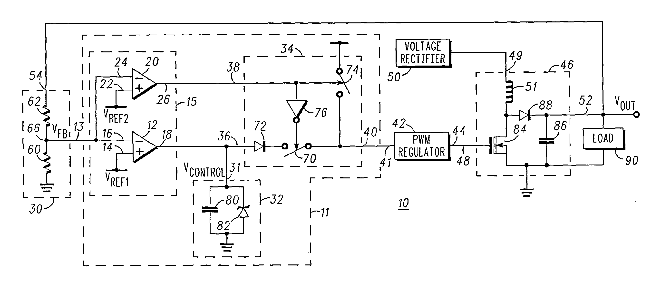
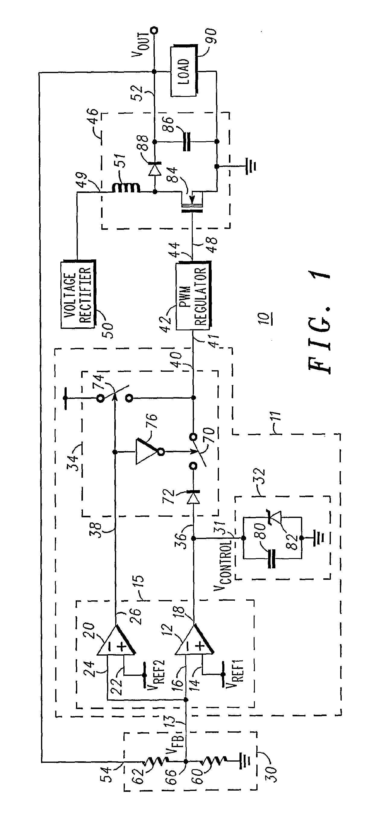
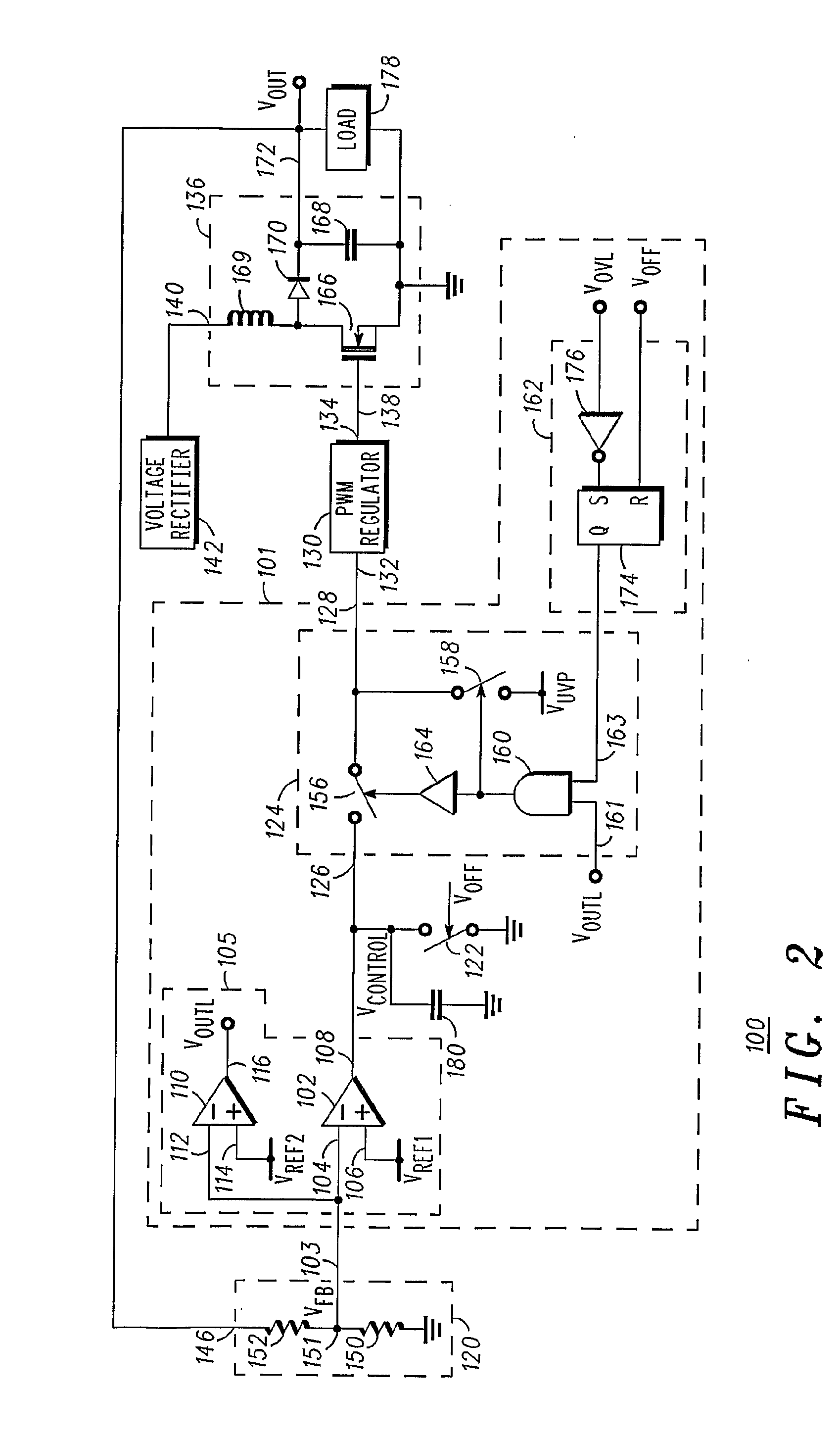
[0008]Generally, the present invention provides a circuit and a method for limiting undervoltages and overvoltages in a regulated output signal. In particular, the circuit and method limit undershoot in the regulated output signal. In accordance with one embodiment, the present invention detects undershoot in an output signal such as, for example, a voltage signal, and transmits a boosted control signal to a regulation section of a regulator circuit. As those skilled in the art are aware, it is desirable for a voltage regulator to output a predetermined or nominal output voltage and for the output voltage to remain substantially constant independent of the load coupled to the regulator. The boosted control signal quickly adjusts the regulated output voltage to compensate for the undershoot. An advantage of a regulator of the present invention is that the original control signal is not modified. Rather, it is prevented from being transmitted to the regulation section. Another advanta...


PUM


Abstract

A voltage regulator (10) having an undervoltage protection circuit 11 and a method for protecting against an output voltage out being less than a predetermined level. The voltage regulator has an undershoot limitation circuit (11) coupled between a feedback network (30) and a regulation section (42). A power factor correction circuit (46) is connected to the regulation section. An output voltage out from the power factor correction circuit (46) is fed back to the feedback network (30), which transmits a portion of the output voltage to the undershoot limitation circuit (11). If the output voltage is greater than the predetermined voltage level, a switching circuit portion (34) of the undershoot limitation circuit (11) transmits a normal control signal to the regulation circuit (42). If the output voltage is less than the predetermined voltage level, the switching circuit portion transmits an enhanced control signal to the regulation circuit. The enhanced control signal quickly brings the output voltage up to at least the minimum desired level.

Description

FIELD OF THE INVENTION[0001]This invention relates, in general, to power supplies and, more particularly, to power factor correction systems.BACKGROUND OF THE INVENTION[0002]Power Factor Correction (“PFC”) systems are typically used within power supply applications requiring AC / DC rectification. Rectifying arrangements for use in such an application may comprise a full wave voltage rectifier, typically in the form of a diode bridge, and a main Switch Mode Power Supply (“SMPS”) to provide regulation of the output waveform. PFC circuits are inserted between the line and the main SMPS to draw a sinusoidal current from the line and to provide Direct Current (“DC”) voltage to the main SMPS. For many systems to operate properly, it is desirable for the output voltage of the PFC circuit to be within a specified range. PFC circuits deliver a squared sinusoidal power that matches an average power demand of the load. Thus, when the power fed to the load is lower than the demand, the output ca...

Claims


Application Information

Patent Timeline
IPC IPC(8): G05F1/40
CPCH02M1/32Y02B70/126H02M1/4225Y02B70/10Y02P80/10
Inventor TURCHI, JOELBASSO, CHRISTOPHE
Owner SEMICON COMPONENTS IND LLC
Why Eureka
Try Eureka