Transmission Line Sensor

a technology of transmission line and sensor, applied in the direction of thermoelectric instruments, instruments, electric devices, etc., can solve the problems of man-made or natural system and/or component failure, severe human suffering and economic losses, and inability to meet the needs of the user, so as to reduce the thermal contact and low cost in manufacturing and installation.

Inactive Publication Date: 2009-01-15
GEORGIOU GEORGE E +4
View PDF6 Cites 302 Cited by
  • Summary
  • Abstract
  • Description
  • Claims
  • Application Information

AI Technical Summary

Benefits of technology

[0006]An overhead high voltage transmission line remote sensor is provided. The remote sensor preferably includes an electronics chamber that transmits overhead high voltage line data to a base station. The remote sensor also preferably includes a clamping mechanism. The clamping mechanism may be adapted to clamp the remote sensor to an overhead high voltage transmission line. The remote sensor may also include a coupling device that couples the electronics chamber to the clamping mechanism. Preferably, the coupling device obtains reduced thermal contact between the clamping mechanism and the electronics chamber.
[0007]O

Problems solved by technology

The electric power supply system is potentially a target for terrorist sabotage because a major disruption of services would virtually paralyze the area affected, leading to panic and chaos.
Natural disasters, such as hurricanes and major thunderstorms, as well as overloading of the power grid, can also inflict severe human suffering and economic losses.
Most system and/or component failures, either man-made or natural, however, develop gradually.
For example, the large scale US northeast blackout of August 2004 was d

Method used


Image

  • Transmission Line Sensor
  • Transmission Line Sensor
  • Transmission Line Sensor

Examples


Embodiment Construction

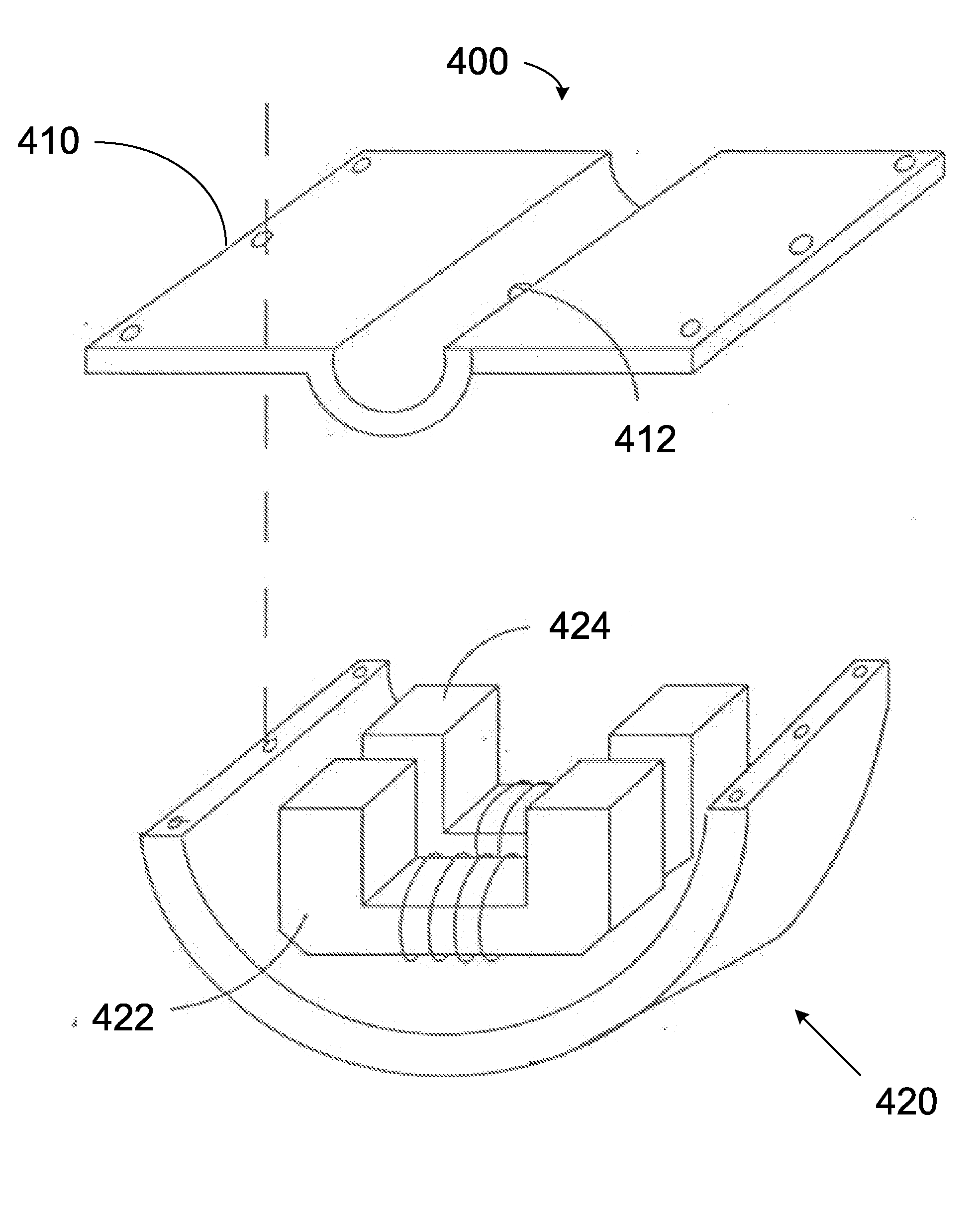
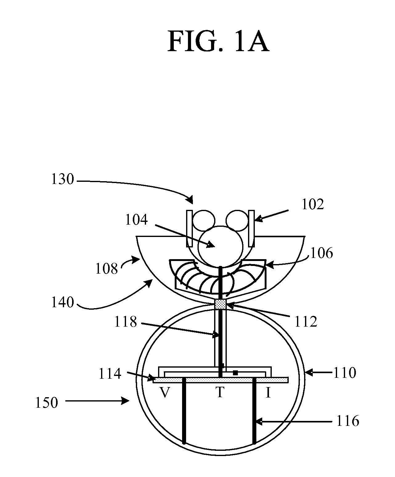
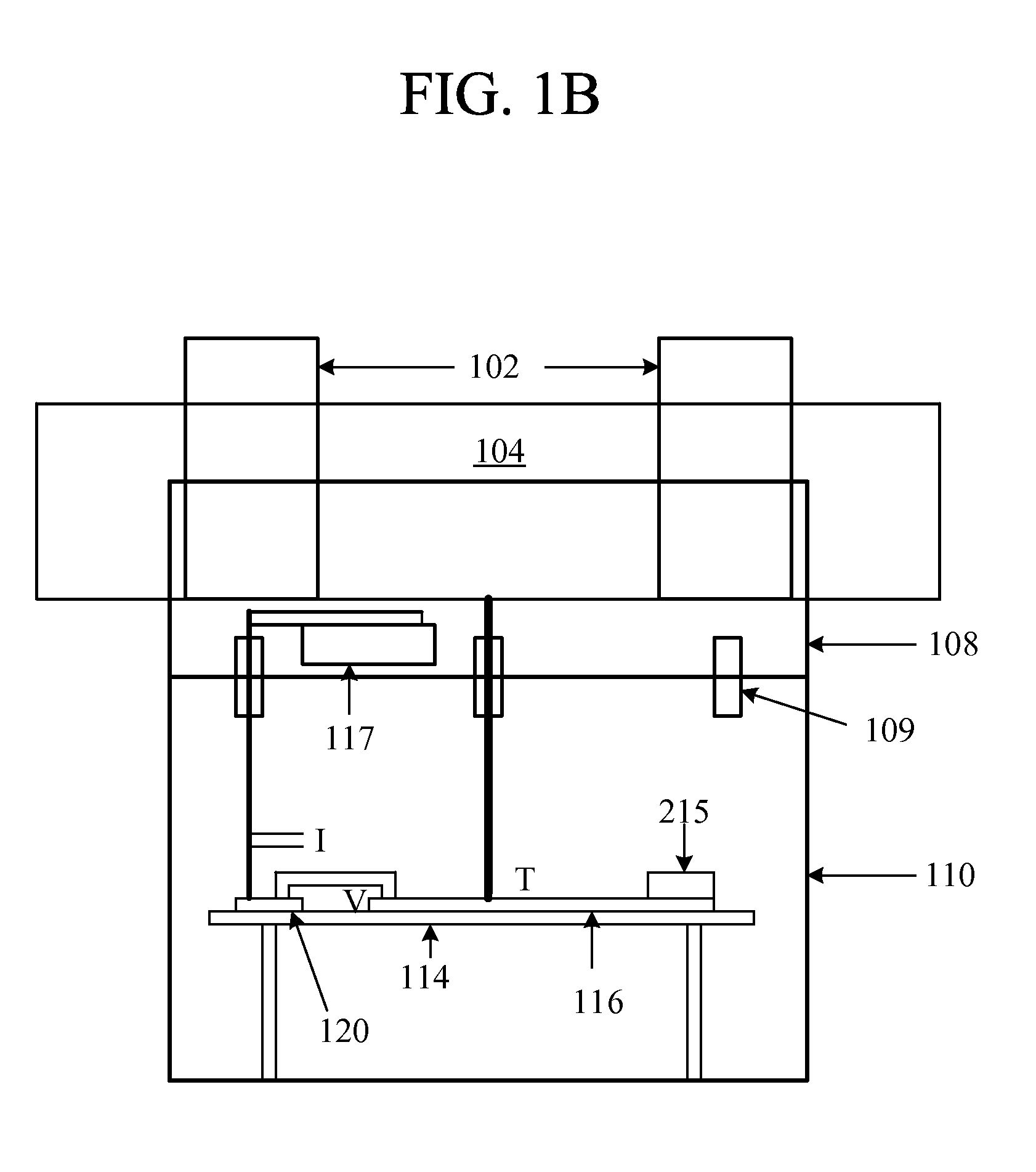
[0027]The objects and advantages of the invention will be apparent upon consideration of the following detailed description, taken in conjunction with the accompanying drawings, in which like reference characters refer to like parts throughout.

[0028]In the following description, for purposes of explanation, specific numbers, materials and configurations are set forth in order to provide a thorough understanding of the invention. It will be apparent, however, to one having ordinary skill in the art that the invention may be practiced without these specific details. In some instances, well-known features may be omitted or simplified so as not to obscure the present invention. Furthermore, reference in the specification to phrases such as “one embodiment” or “an embodiment” means that a particular feature, structure or characteristic described in connection with the embodiment is included in at least one embodiment of the invention. The appearances of phrases such as “in one embodiment...


PUM


Abstract

A system and method in which an overhead high voltage transmission line sensor system is able to measure one or more of temperature, current, and line sag for a conductor within a high voltage transmission line system. The sensor system may be able to clamp to a transmission conductor or splice, harvest power from the transmission line, and/or transmit data corresponding to measurements of current, temperature, and line sag.

Description

CROSS-REFERENCE TO RELATED APPLICATIONS[0001]This application claims the benefit of U.S. Provisional Patent Application Ser. No. 60 / 892,353, filed Mar. 1, 2007, entitled “Overhead High Voltage Transmission Line Remote Sensor”, the entire disclosure of which is hereby incorporated by reference herein.BACKGROUND OF THE INVENTION[0002]The present invention relates in general to transmission line monitoring and in particular to systems and methods for conducting such monitoring in a more efficient and reliable manner than do existing approaches.[0003]The electric power supply system is potentially a target for terrorist sabotage because a major disruption of services would virtually paralyze the area affected, leading to panic and chaos. Natural disasters, such as hurricanes and major thunderstorms, as well as overloading of the power grid, can also inflict severe human suffering and economic losses.[0004]Most system and / or component failures, either man-made or natural, however, develo...

Claims


Application Information

Patent Timeline
IPC IPC(8): G01R19/32
CPCG01R15/14
Inventor GEORGIOU, GEORGE E.CHIN, KEN K.FERRARO, RAYMONDFENG, GUANHUANOE, KAREN GAIL
Owner GEORGIOU GEORGE E
Why Eureka
Try Eureka