
Heat medium heating device and vehicular air-conditioning device including the same

a heating device and a technology for vehicular air conditioning, applied in the direction of indirect heat exchangers, lighting and heating apparatus, stationary plate conduit assemblies, etc., can solve the problems of reducing heat transfer efficiency, limiting the reduction in size, weight, cost, etc., to improve heat transfer efficiency, reduce thermal contact resistance, and secure sealing properties

Inactive Publication Date: 2014-02-20
MITSUBISHI HEAVY INDUSTIRES AUTOMOTIVE THERMAL SYST CO LTD
View PDF3 Cites 19 Cited by
  • Summary
  • Abstract
  • Description
  • Claims
  • Application Information

AI Technical Summary

Benefits of technology

The heat medium heating device described in this patent text has several technical effects. Firstly, it enhances the close contact between different parts of the device, ensuring better heat transfer and sealing properties. Secondly, it reduces the thermal contact resistance between the parts, improving heat transfer efficiency. Finally, it achieves a reduction in size and improved performance of the heat medium heating device. This makes the heat medium heating device ideal for use in vehicle air-conditioning systems, improving the quality, reliability and performance of the vehicle's air-conditioning system.

Problems solved by technology

Unfortunately, in the heat medium heating device disclosed in PTL 1, it is difficult to closely insert and place the PTC heating element to between the partition walls serving as heat transfer surfaces, and the thermal contact resistance between the partition walls and the PTC heating element increases, resulting in a decrease in heat transfer efficiency.
Meanwhile, because it is difficult to arrange PTC heaters in a plurality of layers, the planar area increases, and the heat medium circulation boxes and the special substrate housing box are necessary, which put a limitation on a reduction in size, weight, and cost.

Method used


Image

  • Heat medium heating device and vehicular air-conditioning device including the same
  • Heat medium heating device and vehicular air-conditioning device including the same
  • Heat medium heating device and vehicular air-conditioning device including the same

Examples


Embodiment Construction

[0035]Hereinafter, an embodiment of the present invention is described with reference to FIG. 1 to FIG. 6.

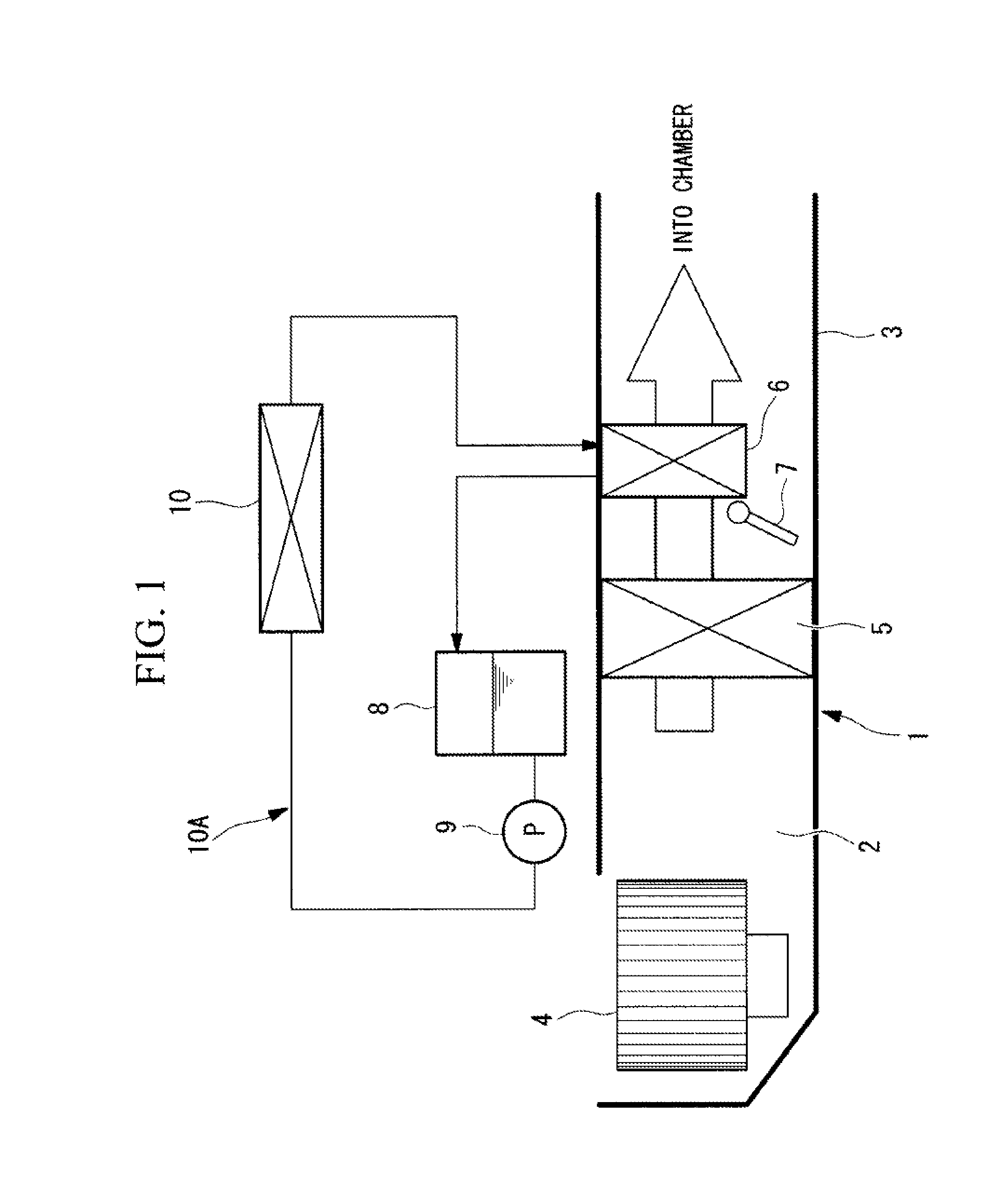
[0036]FIG. 1 is a schematic configuration diagram of a vehicular air-conditioning device including a heat medium heating device according to the embodiment of the present invention.

[0037]A vehicular air-conditioning device 1 includes a casing 3 that forms an air circulation path 2 for taking therein external air or air in a chamber, regulating the temperature thereof, and then guiding the air into the chamber.

[0038]A blower 4, a cooler 5, a heat radiator 6, and an air mix damper 7 are placed in the stated order from the upstream side to the downstream side of the air circulation path 2 inside of the casing 3. The blower 4 suctions external air or air in the chamber, increases the pressure thereof, and sends under pressure the resultant air to the downstream side. The cooler 5 cools the air sent under pressure by the blower 4. The heat radiator 6 heats the air that is cooled whil...


PUM


Abstract

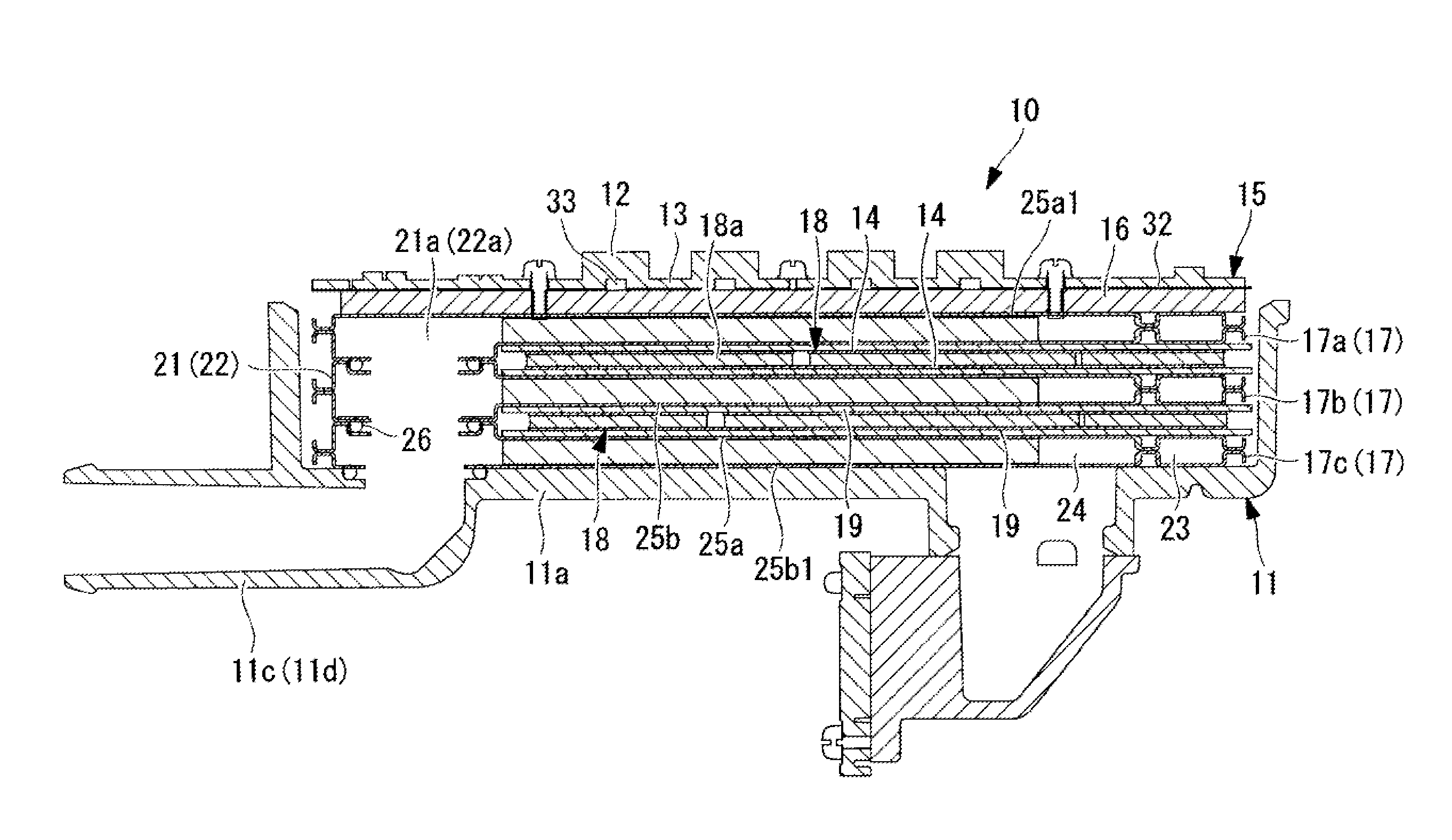
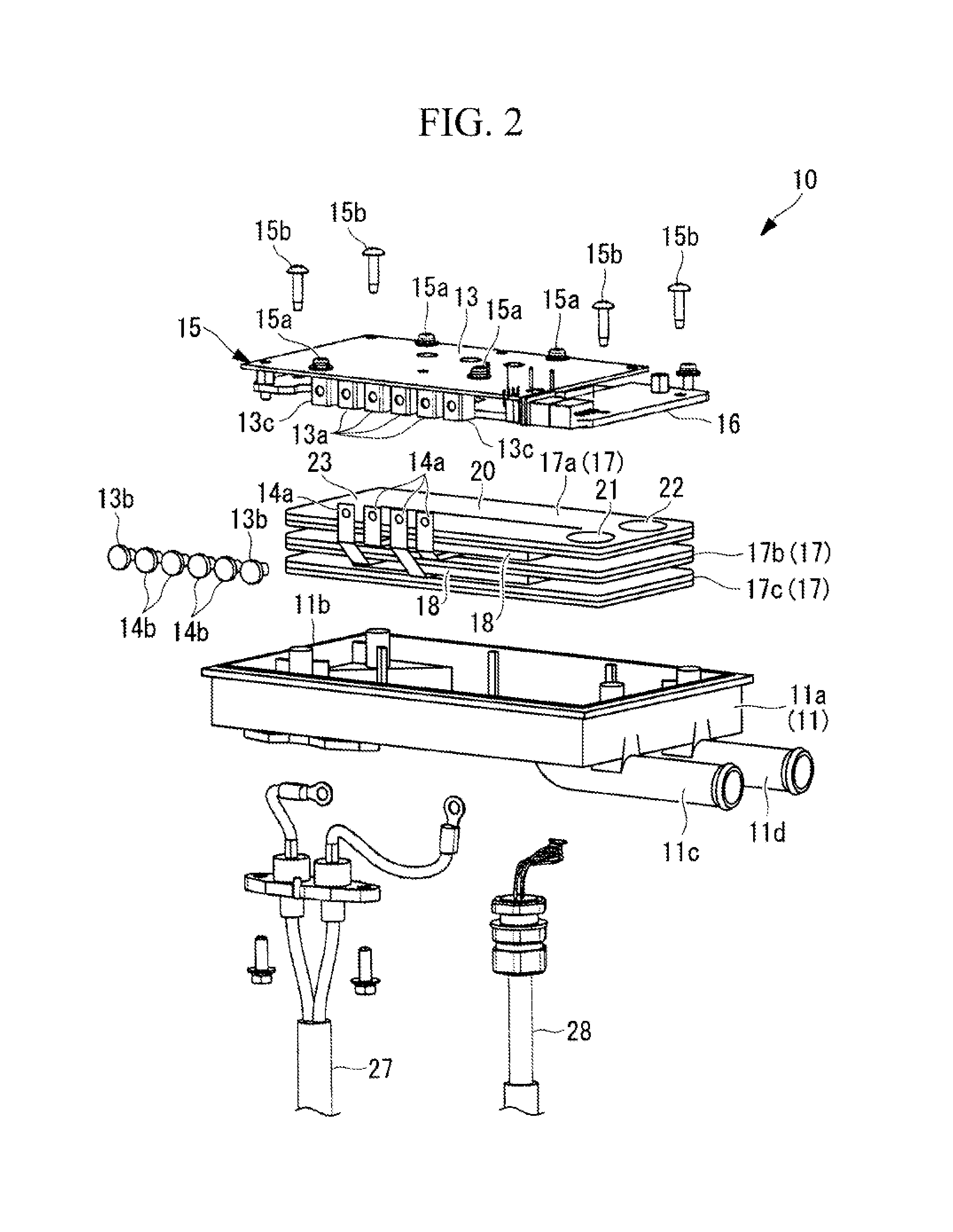
Provided are: a heat medium heating device capable of bringing: flat heat exchange tubes and PTC heaters; and inlet / outlet header parts of the flat heat exchange tubes, into sufficiently close contact with each other, and incorporating these components into a casing; and a vehicular air-conditioning device including the same. In a heat medium heating device, flat heat exchange tubes each including a flat tube part and inlet / outlet header parts and PTC heaters are stacked in layers, and a heat exchange holding member presses the flat heat exchange tubes from one side, whereby the stacked structure is incorporated on an inner bottom surface of a casing. In this configuration, at least uppermost one of the flat heat exchange tubes has one surface pressed by the heat exchange holding member, the one surface being formed into a planar shape in which the flat tube part and the inlet / outlet header parts are flattened.

Description

TECHNICAL FIELD[0001]The present invention relates to a heat medium heating device that heats a heat medium using a PTC heater and a vehicular air-conditioning device including the heat medium heating device.BACKGROUND ART[0002]In vehicular air-conditioning devices applied to electric automobiles, hybrid automobiles, and the like, it is known to use a positive temperature coefficient (PTC) heater for a heat medium heating device that heats a heat medium to be heated serving as a heat source for air heating. The PTC heater includes a positive temperature thermistor (hereinafter referred to as PTC element) as its heating element. With regard to such a heat medium heating device, PTL 1 discloses that: a housing includes an inlet and an outlet of a heat medium; a large number of partition walls for dividing the inside of the housing into a heating chamber and a circulation chamber of the heat medium are provided; a PTC heating element is inserted and placed in the heating chamber sectio...

Claims


Application Information

Patent Timeline
Patent Type & Authority Applications(United States)
IPC IPC(8): B60H1/22F24H3/02
CPCF24H3/022B60H1/2225B60H1/2221F24H1/009F24H3/102F24H9/1872B60H2001/2271B60H2001/2278F28D9/0056
Inventor KOMINAMI, SATOSHIKUNIEDA, NAOTO
Owner MITSUBISHI HEAVY INDUSTIRES AUTOMOTIVE THERMAL SYST CO LTD
Learn More