Excimer lamp

A technology of excimer lamps and discharge vessels, applied in the field of excimer lamps, can solve the problems of broken discharge vessels 2, achieve the effects of preventing peeling, inhibiting deterioration, and improving close contact

Active Publication Date: 2009-09-23
USHIO DENKI KK
View PDF1 Cites 9 Cited by
  • Summary
  • Abstract
  • Description
  • Claims
  • Application Information

AI Technical Summary

Problems solved by technology

However, such an elongated excimer lamp 1 has a problem that the discharge vessel 2 is broken during lighting.

Method used


Image

  • Excimer lamp
  • Excimer lamp
  • Excimer lamp

Examples


Embodiment Construction

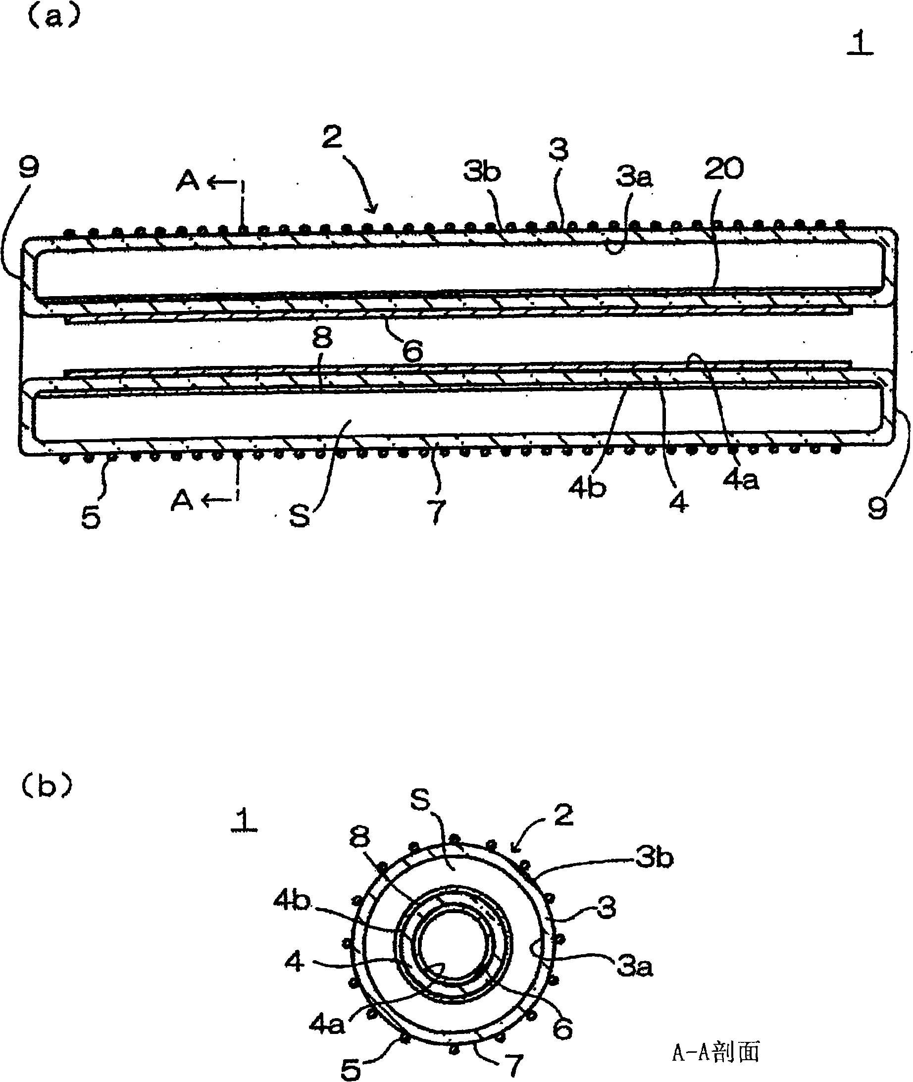
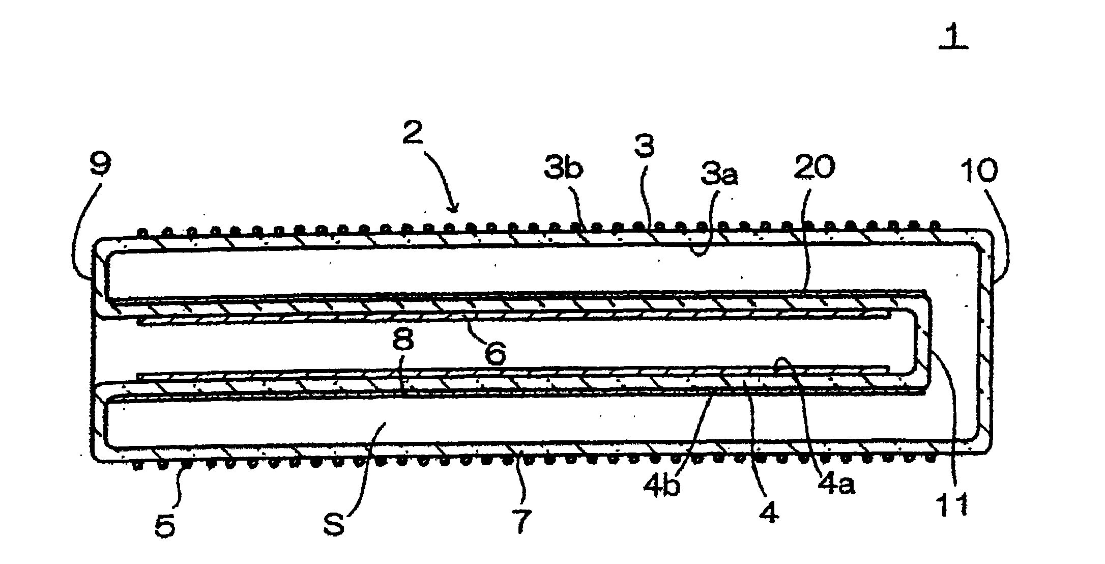
[0025] figure 1 It is an explanatory cross-sectional view showing the structure of the excimer lamp 1, (a) is a transverse cross-sectional view showing a cross-section along the longitudinal direction of the discharge vessel 2, and (b) is a cross-sectional view taken along line A-A of (a).

[0026] The excimer lamp 1 has a discharge vessel 2 composed of a cylindrical outer tube 3 and a cylindrical inner tube 4 . The length of the discharge vessel 2 in the tube axis direction is, for example, 800 to 1600 mm, the diameter of the outer tube 3 is 25 to 40 mm, and the diameter of the inner tube 4 is 15 to 30 mm.

[0027] The diameter of the inner tube 4 is configured to be smaller than that of the outer tube 3 , and the inner tube 4 is disposed inside the outer tube 3 . Since the inner tube 4 is arranged along the tube axis of the outer tube 3 , the discharge vessel 2 has a double tube structure in which the outer tube 3 and the inner tube 4 are arranged in the coaxial direction. ...


PUM


Abstract

The invention provides an excimer lamp which generates excimer discharge in discharge space to radiate vacuum ultraviolet light. Melted quartz glass forms a part of a discharge container. The excimer lamp (1) has a discharge container (2) made of quartz glass and composed of a dual pipe of which the inside pipe (4) and the outside pipe (3) are disposed in the coaxial direction; a pair of electrodes (5), (6) is disposed in a state of the quartz glass forming the discharge container (2); xenon gas is sealed in the discharge space (S); excimer discharge happens in the discharge space (S) of the discharge container (2). The invention is characterized in that the inside pipe (4) is made from melted quartz glass and the outside pipe (3) is made from synthesized quartz glass.

Description

[0001] technology area [0002] The present invention relates to an excimer lamp comprising a discharge vessel made of quartz glass, a pair of electrodes interposed by the quartz glass forming the discharge vessel, and excimer discharge occurring inside the discharge vessel. Background technique [0003] In recent years, it has been developed to irradiate the object to be processed with vacuum ultraviolet light with a wavelength of 200nm or less on the object made of metal, glass and other materials, and to treat the object to be processed through the action of the vacuum ultraviolet light and the ozone generated thereby. Technologies, such as cleaning treatment technology to remove organic pollutants adhering to the surface of the object to be processed, or oxide film formation treatment technology to form an oxide film on the surface of the object to be processed, are being put into practical use. [0004] As a device for irradiating vacuum ultraviolet light, for example, an...

Claims


Application Information

Patent Timeline
Patent Type & Authority Applications(China)
IPC IPC(8): H01J65/00H01J61/34
CPCH01J5/50H01J9/247H01J61/125H01J61/305H01J61/35H01J65/046
Inventor 藤泽繁树森本幸裕菱沼宣是
Owner USHIO DENKI KK
Why Eureka
Try Eureka