[0008]Further, it is another objective of the present invention to provide a wire connector that provides highly reliable electrical connections.
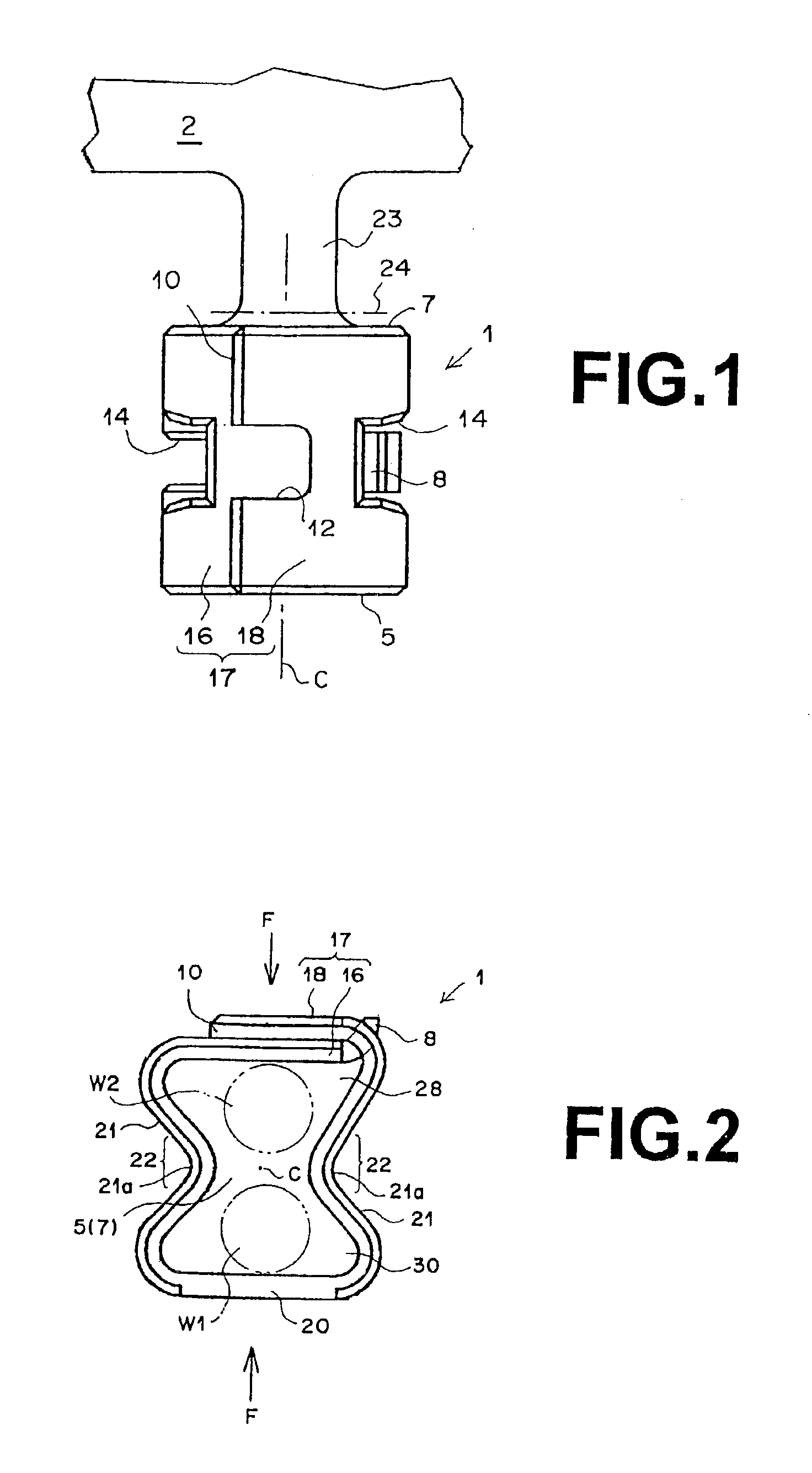
[0027]The wire connector of the present invention comprises a closed ring formed by bending a
metal plate to bring both ends thereof together to form an
enclosure; and depressions that are recessed towards the interior of the closed ring along an axis thereof that passes through the open ends at both sides of the
coupling portion of the metal plates so that the depressions face each other; wherein electrical connections are established among a plurality of wires that are inserted through the open ends of the closed ring by being brought into contact with each other due to deformation of the depressions from pressure applied to the closed ring in a direction that causes the
coupling portion of the metal plates and a wall of the closed ring opposite thereto to approach each other. Therefore, it exhibits the following effects.
[0028]That is, because the wires are fixed to each other by crimping the closed ring, a compact wire connector having a small wire collection space and sufficient connection strength is obtained. In addition, by the depressions being formed in the closed ring, the wires can be crimped together with a comparatively small force employing pliers or a manual press. Therefore, the shock load imparted on the wires to be connected during the connection of the wires is small, and the risk of damaging a member to which the shock is transmitted via the wires is small. Further, wires of a broader range of diameters can be connected to each other than with a conventional press contact connection.
[0032]In addition, the
mechanical strength of the connector after compression is high, and not likely to deform.
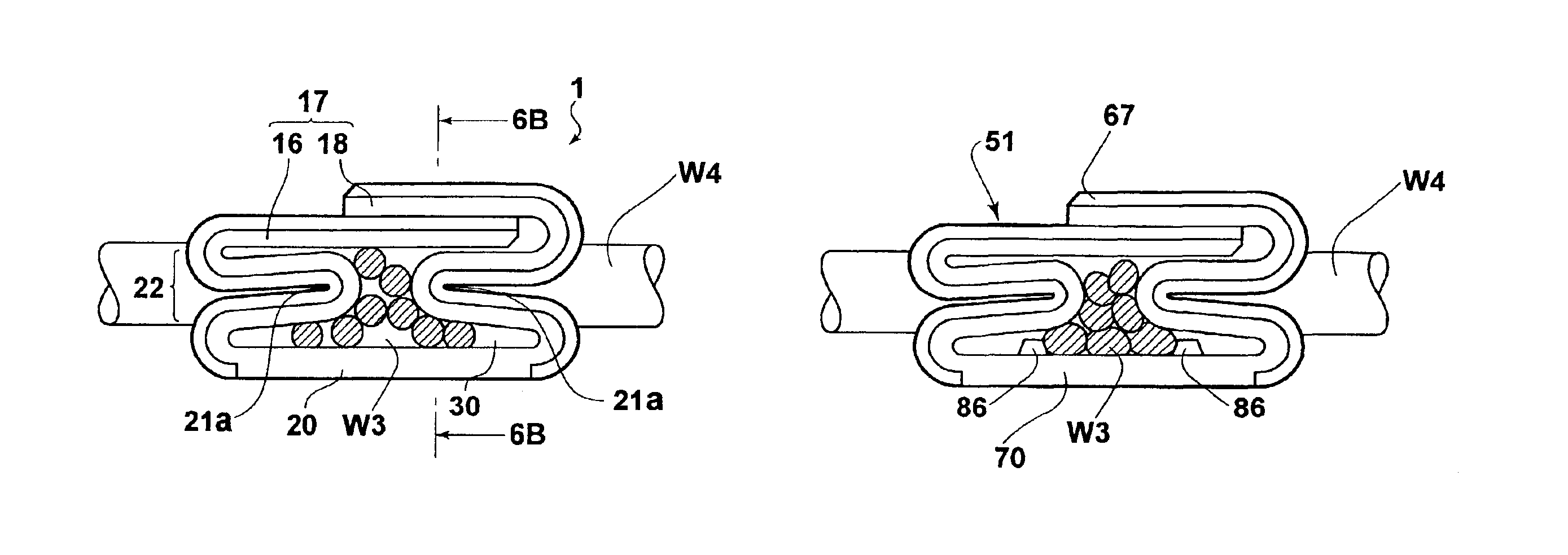
[0033]In the case that at least one pair of beads is formed on the surface of the wall of the closed ring opposite the
coupling portion of the metal plates, the beads extending towards the coupling portion of the metal plates while being separated from each other, when a plurality of wires is to be connected, the cores thereof are controlled by the pair of beads so as to not spread outwardly. That is, the beads gather the cores towards the center of the wire connector, thereby improving the
close contact property of the cores during connection of the wires, and consequently the reliability of the
electrical connection. Further, the beads are capable of directly pressing on a portion of the cores during the connection of the wires, improving the reliability of the
electrical connection.
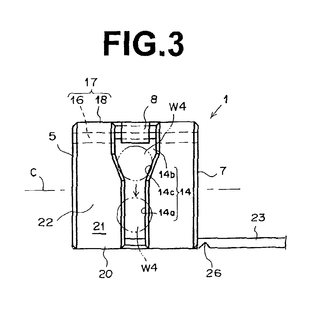
[0034]In the case that the wall of the closed ring, opposite the coupling portion of the metal plates, is extended to have an extended portion that protrudes from the opening of the closed ring, the cores of the wires can be temporarily placed on the extended portion, then inserted into the open end. Therefore, the workability of the
insertion of the cores to the closed ring is improved during the operation of connecting the wires. Also at this time, the outer coverings of the covered wires may be placed to abut the edge of the extended portion to perform positioning of the covered wires, further improving the workability. Further, if during the connection of the wires, covered portions of the wires are erroneously inserted within the open ends, this defect can be easily discriminated by
visual inspection of the extended portion. In other words, a correct connection state can be confirmed easily by
visual inspection of the wires on the extended portion.

