Magnetoresistive Magnetic Field Sensor Structure

a magnetic field and sensor technology, applied in the direction of magnets, magnets, instruments, etc., can solve the problem of relativly small amount of effort in process engineering

Active Publication Date: 2009-01-15
INFINEON TECH AG
View PDF12 Cites 74 Cited by
  • Summary
  • Abstract
  • Description
  • Claims
  • Application Information

AI Technical Summary

Benefits of technology

[0007]In accordance with further embodiments, the present invention provides a magnetic field detection device comprising a first magnetoresistive element in a spin-valve arrangement with a first reference layer structure with a first reference magnetization direction, and a second magnetoresistive element in a spin-valve arrangement with a second reference layer structure with a second reference magnetization direction, wherein the first and second magnetoresistive elements are arranged in a layer stack vertically above each other and galvanically isolated from each other by an intermediate layer, and wherein the first and second reference magnetization directions are opposed to each other, and wherein the two magnetoresistive elements are connected in a bridge circuit such that, due to an inverse change in the resistance values of the two magnetoresistive elements, a difference signal is detectable proportionally to the magnetic field and/or a magnetic field change between two bridge arms of the bridge circuit.
[0008]Still further embodiments provide a method of producing a magnetic field senso

Problems solved by technology

GMR layer systems are commonly operated in the CIP configuration, which is associated with a relatively small amount of

Method used


Image

  • Magnetoresistive Magnetic Field Sensor Structure
  • Magnetoresistive Magnetic Field Sensor Structure
  • Magnetoresistive Magnetic Field Sensor Structure

Examples


Embodiment Construction

[0026]With respect to the subsequent description it should be noted that in the various embodiments functional elements which are identical or have identical actions will be designated by identical reference numerals, and that the descriptions of these functional elements are mutually interchangeable in the various embodiments represented below.

[0027]Indications of directions such as “right-hand”, “left-hand”, “top”, “bottom” included in explanations of the accompanying figures relate to the respective planes of projection. Indications such as “vertical”, “horizontal” or “lateral” shall refer to a magnetic field-sensitive component or chip surface in the following.

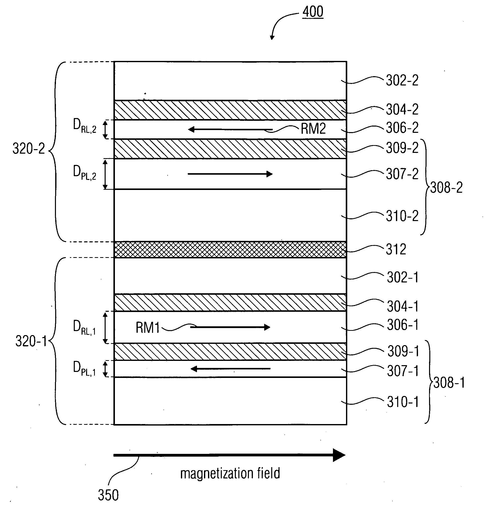
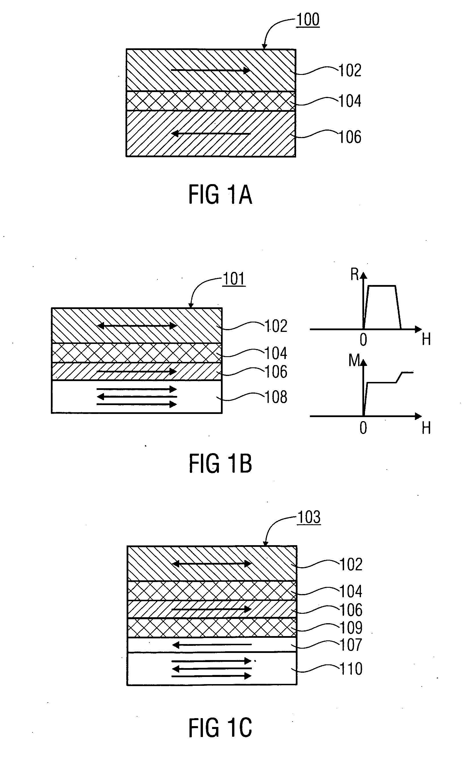
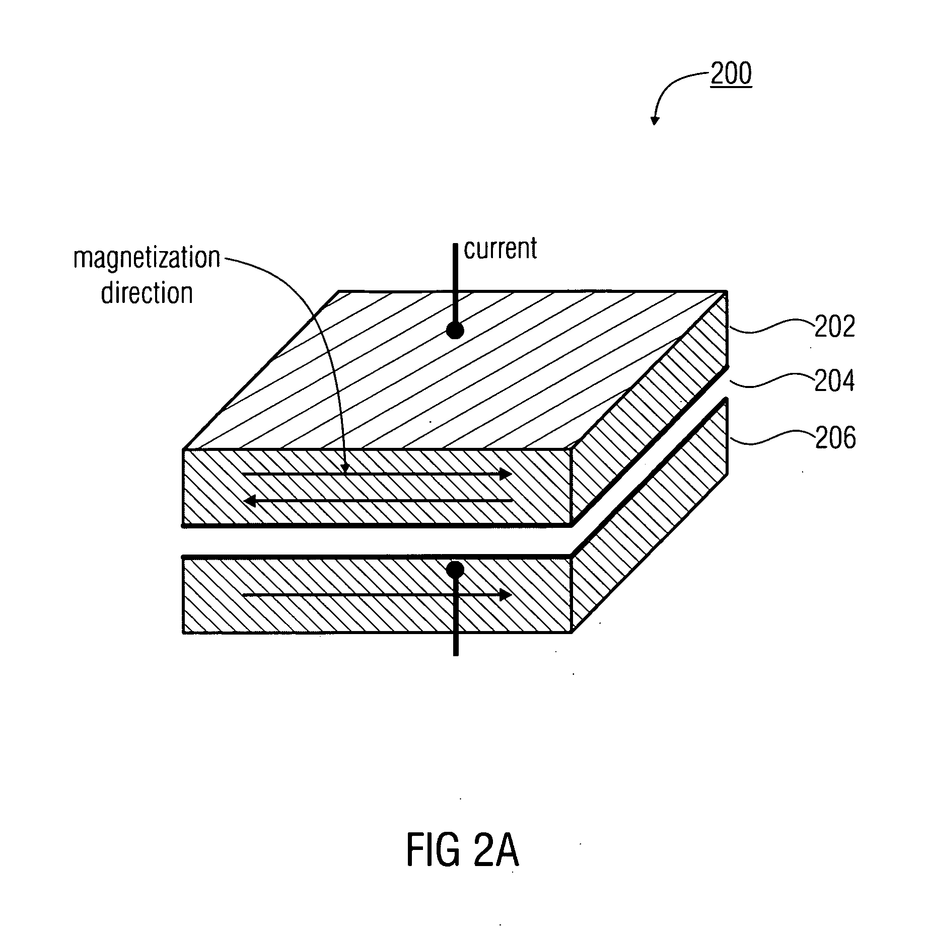
[0028]Before giving a detailed description of embodiments of the present invention with reference to FIGS. 3 to 13, xMR structures will be briefly addressed in general below with reference to FIGS. 1 to 2. The term xMR structure is understood to mean GMR structures and TMR structures in the description which follows. In pa...


PUM

PropertyMeasurementUnit
Fractionaaaaaaaaaa
Magnetic fieldaaaaaaaaaa

Abstract

A magnetic field sensor structure including a first magnetoresistive element in a spin-valve arrangement with a first reference layer structure with a first reference magnetization direction and a second magnetoresistive element in a spin-valve arrangement with a second reference layer structure with a second reference magnetization direction, wherein the first and second magnetoresistive elements are arranged in a layer vertically above each other and galvanically isolated from each other by an intermediate layer, and wherein the first and second reference magnetization directions are different.

Description

[0001]This application claims priority to German Patent Application 10 2007 032 867.4, which was filed Jul. 13, 2007 and is incorporated herein by reference.TECHNICAL FIELD[0002]The present invention relates to a magnetoresistive magnetic field sensor structure on the basis of spin-valve structures, and to methods of manufacturing the same.BACKGROUND[0003]Detecting small magnetic fields by means of large magnetoresistance changes while using up as little chip surface area as possible and with a low level of manufacturing-process complexity is becoming increasingly important for applications in automotive and industrial electronics. In this context, it is particularly important to achieve compatibility and optimization of parameter swing, or signal swing (change in the magnetoresistance as a function of a change in the magnetic field), chip surface area, manufacturing-process complexity, current consumption, etc.[0004]In sensor technology, currently GMR structures (GMR=giant magnetor...

Claims


Application Information

Patent Timeline
IPC IPC(8): G01R33/02H01F7/06
CPCB82Y25/00Y10T29/4902H01L27/22G01R33/093H10B61/00H10N59/00
Inventor RABERG, WOLFGANGZIMMER, JUERGEN
Owner INFINEON TECH AG
Why Eureka
Try Eureka