Method and system for configuring a monitoring device for monitoring a spatial area

a monitoring device and a technology for spatial areas, applied in the field of methods and systems for configuring monitoring devices for spatial areas, can solve the problems of high cost of such protection, inability to adapt monitoring and protective spaces to changing working environments, and inability to stop machines or installations or otherwise rendered harmless, etc., to achieve simple, convenient and failsafe

Active Publication Date: 2009-01-15
PILZ (COMPANY)
View PDF13 Cites 48 Cited by
  • Summary
  • Abstract
  • Description
  • Claims
  • Application Information

AI Technical Summary

Benefits of technology

[0015]Against this background, it is an object of the present invention to provide a method for configuring a monitoring device of the aforementioned type so that monitoring areas can be configured in a simple, convenient and failsafe manner.

Problems solved by technology

As soon as a person or an object breaks through the barrier, the machine or installation is stopped or otherwise rendered harmless.
In the case of complex machines and installations, the expenditure for such protection can become very high.
Moreover, they can only monitor a straight area between light transmitter and light receiver so that a plurality of light barriers, light curtains et cetera are needed in order to protect a complex working area all around.
In addition mechanical barriers and conventional light barriers, light curtains et cetera only provide limited flexibility so that the adaptation of the monitoring and protective spaces to changing working environments is expensive.
On the other hand, the high flexibility due to the virtual protection areas provides difficulties when setting up and configuring the monitoring device at a machine or installation.
However, this does not apply to the monitoring devices with virtual protection spaces.
Otherwise, undetected break-ins into the hazardous area of the monitored installation and thus grave injuries and personal damage could occur.
However, this method for setting up monitoring areas is not optimal because the setting-up requires physical access to the marking points.
In addition, DE 41 13 992 A1 does not disclose any mechanisms for ensuring failsafe configuration of a monitoring area.

Method used


Image

  • Method and system for configuring a monitoring device for monitoring a spatial area
  • Method and system for configuring a monitoring device for monitoring a spatial area
  • Method and system for configuring a monitoring device for monitoring a spatial area

Examples


Embodiment Construction

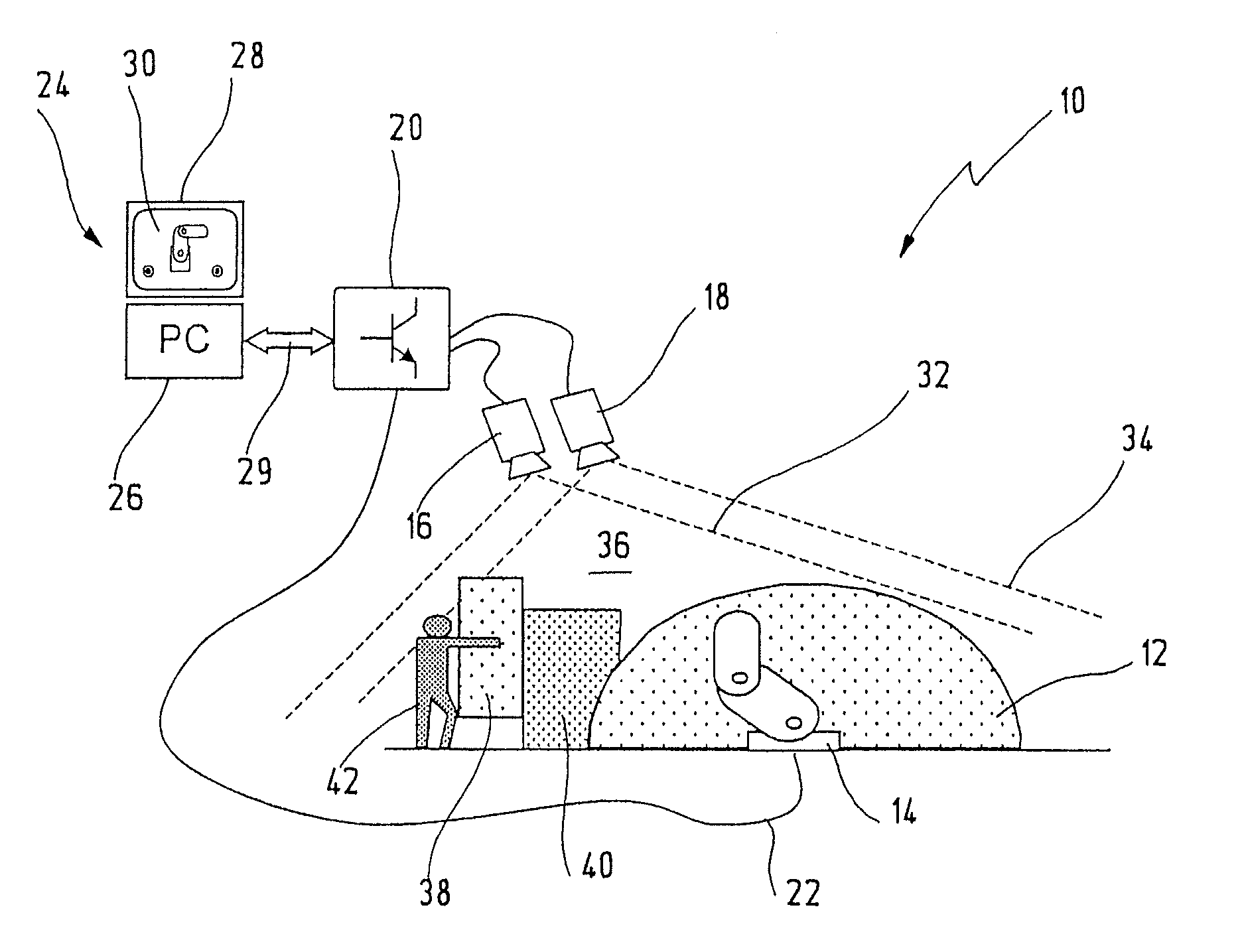
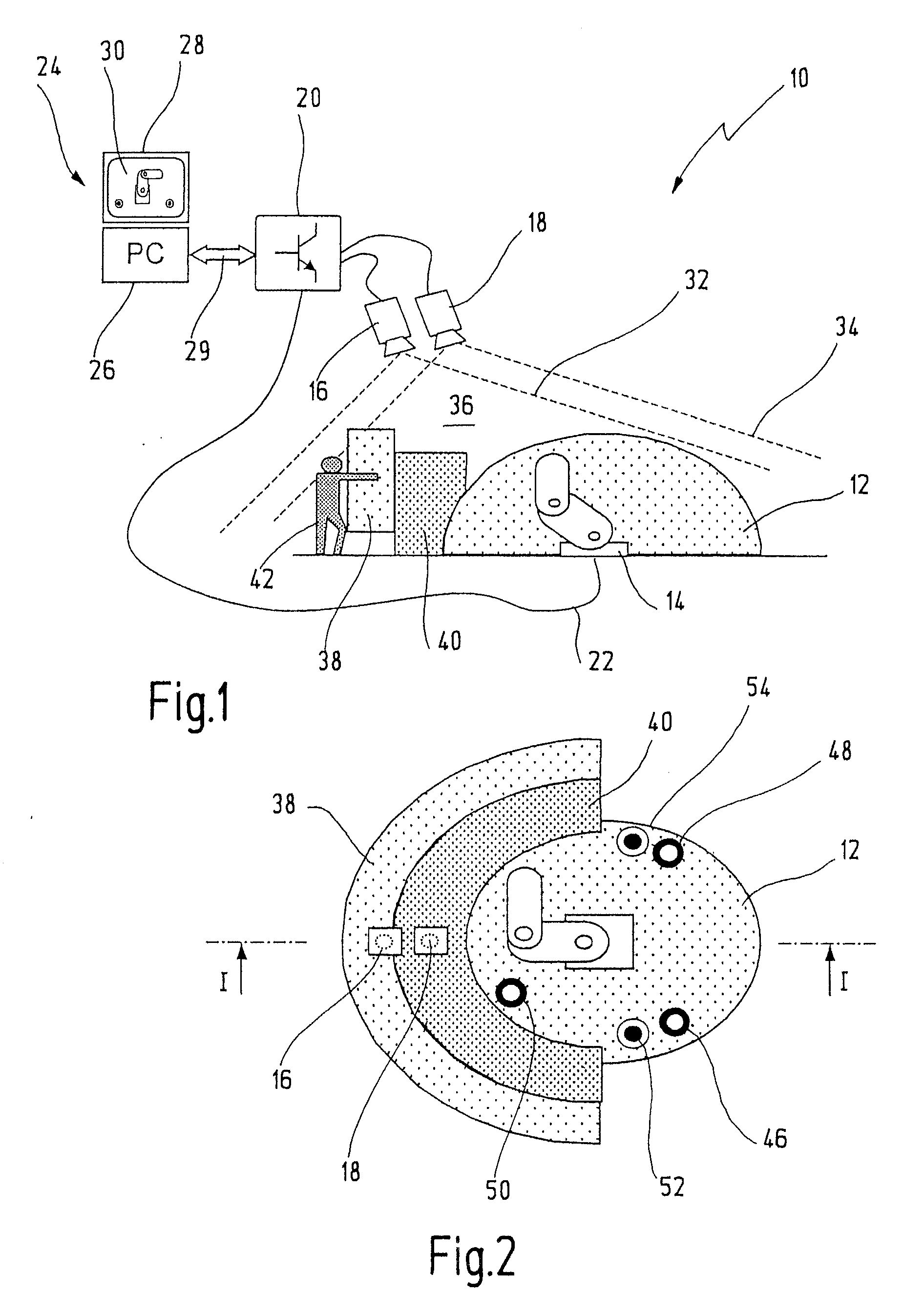
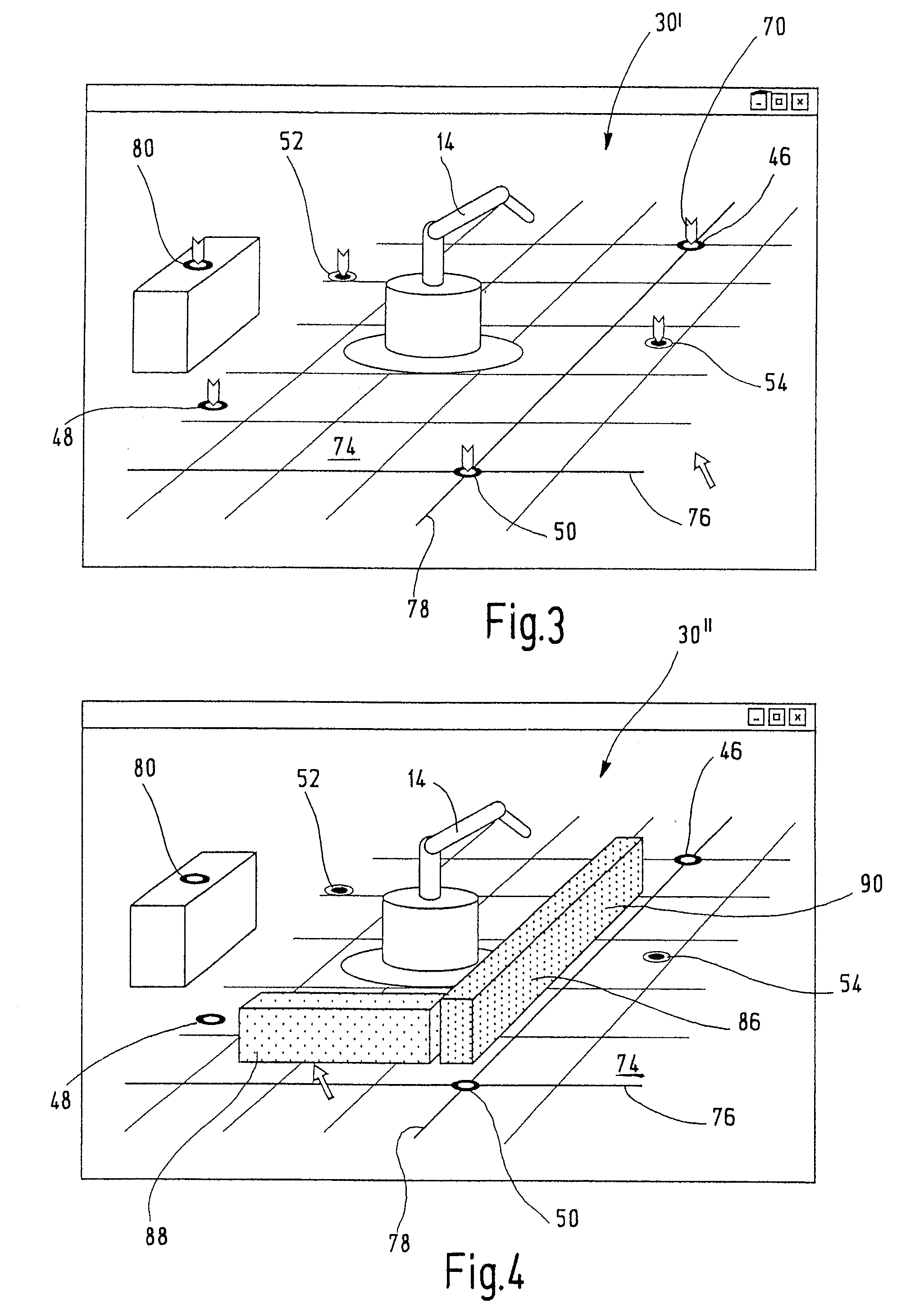
[0057]In FIG. 1, an illustrative embodiment of a monitoring device in accordance with the present invention is designated by the reference number 10 in its totality. The monitoring device 10 is here used for monitoring the hazardous working area 12 of a robot 14. This is a preferred illustrative application of the novel monitoring device. However, the invention is not restricted to this and can also be used for protecting other machines and installations.

[0058]In addition, the present invention can also be used in other fields, such as for configuring monitoring areas for monitoring valuable objects (strongroom monitoring et al.) and / or for monitoring entry areas in public buildings, at airports etc. It can also be used for configuring monitoring areas as part of quality control and quality assurance.

[0059]The monitoring device 10 here comprises two image recording units 16, 18 which, for the sake of simplicity, will be called cameras in the following. In a particularly preferred em...


PUM


Abstract

A monitoring device for monitoring a spatial area comprises at least one image recording unit. A three-dimensional image of the spatial area is recorded and displayed in order to configure. the monitoring device. A configuration plane is defined using a plurality of spatial points which have been determined within the three-dimensional image. Subsequently, at least one variable geometry element is defined relative to the configuration plane. A data record which represents a transformation of the geometry element into the spatial area is generated and transferred to the monitoring device.

Description

CROSS REFERENCES TO RELATED APPLICATIONS[0001]This application is a continuation of international patent application PCT / EP2006 / 011963, filed on Dec. 13, 2006 designating the U.S., which international patent application has been published in German language as WO 2007 / 079883 A2 and claims priority from German patent application DE 10 2005 063 217.3, filed on Dec. 22, 2005. The entire contents of these priority applications are incorporated herein by reference.BACKGROUND OF THE INVENTION[0002]The present invention relates to a method and a system for configuring a monitoring device for monitoring a spatial area, in particular for configuring a monitoring device for failsafely monitoring a working area of a machine or installation, which is operated in an automated manner.[0003]Working areas of machines or installations operating in automated manner are traditionally safeguarded by mechanical barriers (protective fences, protective doors) and / or by light barriers, light curtains, lase...

Claims


Application Information

Patent Timeline
Patent Type & Authority Applications(United States)
IPC IPC(8): H04N13/02H04N7/18
CPCF16P3/14F16P3/142G06T7/0075G06T7/0008G06T7/593H04N13/204H04N23/63G06T15/00F16P3/00
Inventor DOETTLING, DIETMARFUCHS, OLIVERSUGRUE, JAMES
Owner PILZ (COMPANY)
Why Eureka
Try Eureka