
Picture display unit

Inactive Publication Date: 2009-01-15
TOYODA GOSEI CO LTD
View PDF2 Cites 2 Cited by
  • Summary
  • Abstract
  • Description
  • Claims
  • Application Information

AI Technical Summary

Benefits of technology

[0007]An advantage of some aspects of the invention is to provide a picture display device able to maintain the picture display even in the absence of external force, and affording reduced energy consump

Problems solved by technology

However, a drawback of the picture display device is that the colloidal crystals cannot maintain their deformed state unless voltage continues to be applied, so power consumption is considerable.
Another problem is that since the picture display device cannot display black, the content which it is possible to display is limited.

Method used


Image

  • Picture display unit
  • Picture display unit
  • Picture display unit

Examples


Embodiment Construction

[0037]The preferred modes for carrying out the present invention will be discussed below.

(1) General Configuration of Picture Display Device 10

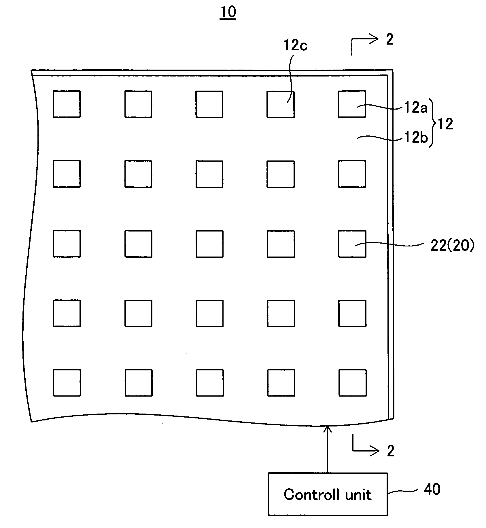
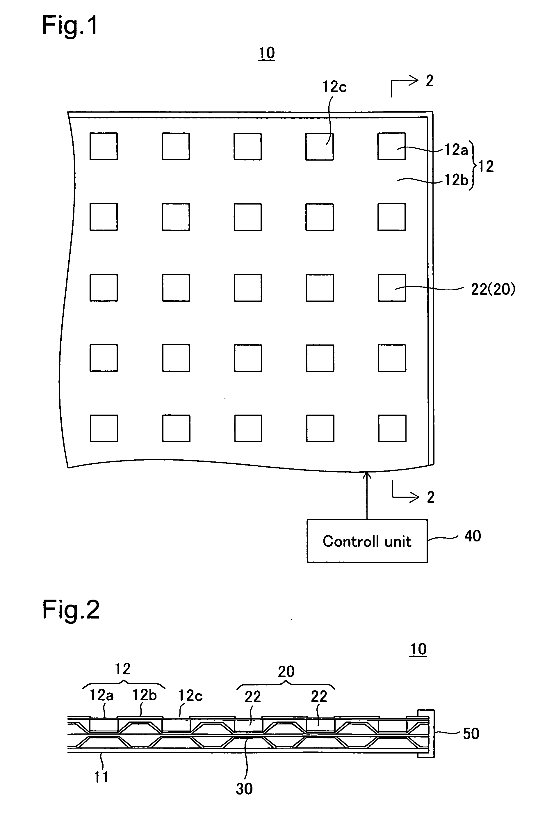
[0038]FIG. 1 is a plan view showing a picture display device 10 which pertain s to a first embodiment of the present invention; and FIG. 2 is a sectional view taken along line 2-2 in FIG. 1. In FIG. 2, the picture display device 10 includes a support substrate 11; a display panel 12 arranged parallel to the support substrate 11 with a prescribed gap therebetween; a display mechanism 20 positioned between the support substrate 11 and the display panel 12 and composed of a multitude of display elements 22; shape deformation portions 30 for applying force in order to bring about deformation of the display elements 22 of the display mechanism 20; a control unit 40 (FIG. 1) which outputs an actuation signal to the shape deformation portions 30; and a frame body 50 positioned bordering the sides of the display mechanism 20. In the design of this pi...


PUM


Abstract

A picture display device includes display elements reflecting specific wavelengths of visible light; and shape deformation portions for inducing elastic deformation of the display elements. The individual display elements have colloidal particles arrayed at regular spacing, and an elastically deformable filler material intervening between the colloidal particles. The shape deformation portion includes a shape retention component formed of a material capable of reversible plastic deformation by external force.

Description

[0001]This application claims the benefit of and priority from Japanese Application No. 2007-184591 filed Jul. 13, 2007, and No. 2007-184606 filed Jul. 13, 2007, the contents of which are incorporated herein by reference.BACKGROUND OF THE INVENTION[0002]1. Field of the Invention[0003]The present invention relates to a picture display device for displaying images through reflection of specific wavelengths of visible light by a periodic structure produced by colloidal particles.[0004]2. Description of the Related Art[0005]Picture display devices of this kind known is disclosed, for example, in JP 2007-11112 A. In the device, the pixels are composed of colloidal crystals filled with polymer gel; absorption and release of a solvent by the polymer gel is brought about through application of electrical voltage to the pixels thereby inducing the colloidal crystals to undergo changes in volume through expansion and contraction. This causes the spacing between the colloidal crystals to chang...

Claims


Application Information

Patent Timeline
IPC IPC(8): G02F1/29
CPCG02B26/001
Inventor ANDO, HIROAKIMIYAZAKI, TAKESHITAKEUCHI, HIROMITSUNAKAMURA, HIROSHIISHII, MASAHIKO
Owner TOYODA GOSEI CO LTD
Learn More