
Lens drive device

a drive device and lens technology, applied in the direction of printers, instruments, cameras, etc., can solve the problems of easy vibration or impact easy deformation or breakage of plastic parts, and easy stroke failure of the lens drive device, so as to achieve superior vibration proofing and impact resistance

Active Publication Date: 2009-01-15
SANKYO SEIKI MFG CO LTD
View PDF1 Cites 40 Cited by
  • Summary
  • Abstract
  • Description
  • Claims
  • Application Information

AI Technical Summary

Benefits of technology

The present invention provides a lens drive device with improved vibration proofing and impact resistance. The device includes a movable lens body and a support body which movably supports the lens body through a plate spring in an optical axis direction. The plate spring has an arm part between the outer side connecting part and the inner side connecting part. The arm part comprises a meandering part which has a plurality of extending parts that are extended in a radial direction and connected through inner and outer side turning portions. The arm part is designed to have a meandering part even in small regions, which allows for a larger number of extending parts and thus more impact resistance. The width dimension of the outer side turning portion is wider than the width dimension of the inner side turning portion to enhance rigidity and prevent damage to the outer side turning portion. The meandering part can have a gap space dimension between the inner side connecting part and the inner side turning portion that is wider than the gap space dimensions between the inner side and outer side turning portions to further improve impact resistance. The width dimension of the inner connecting portion is wider than the width dimension of the meandering part to prevent damage to the arm part when a large load is applied to the inner connecting portion.

Problems solved by technology

Further, a portable device is easily subjected to vibration or impact because of property of being portably carried, but the vibration or the impact is absorbed by the arm part.
In addition, when the lens drive device receives a strong impact such as a dropping impact to cause the movable lens body to be moved intensely in a direction perpendicular to the optical axis direction or in a tilt direction, plastic deformation or breaking may easily occur in the plate spring and malfunction such as stroke failure may easily occur in the lens drive device.

Method used


Image

  • Lens drive device
  • Lens drive device
  • Lens drive device

Examples


Embodiment Construction

[0028]A lens drive device in accordance with an embodiment of the present invention will be described below with reference to the accompanying drawings. A lens drive device described below may be mounted on various electronic devices in addition to a cellular phone with camera. For example, the lens drive device may be used in a thin type digital camera, a PHS, a PDA, a bar code reader, a monitoring camera, a camera for confirming a rear side of a car, a door having an optical authentication function and the like.

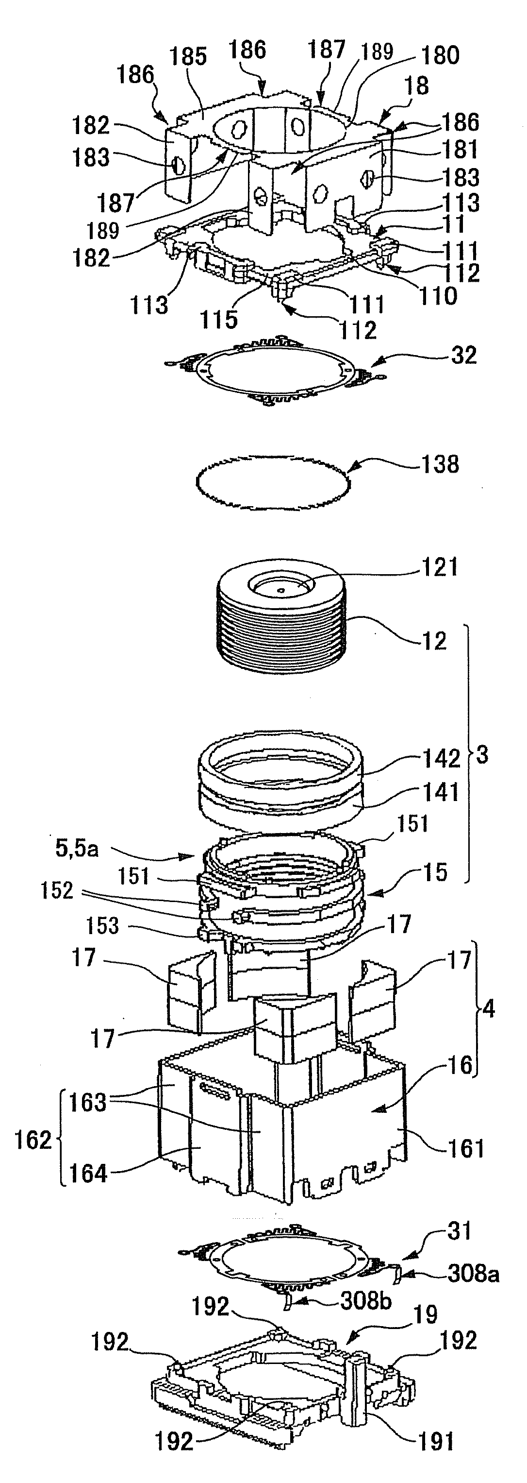
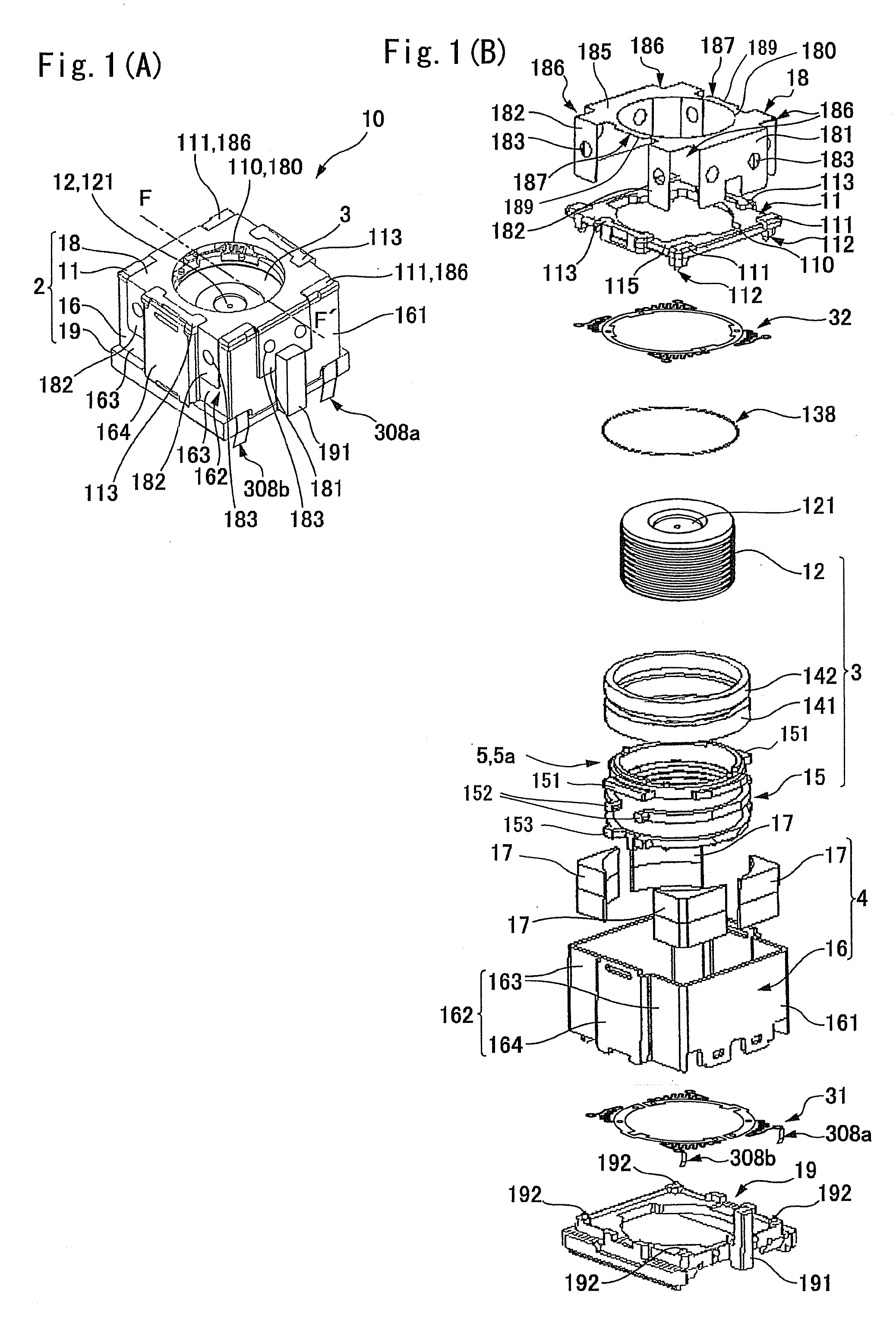
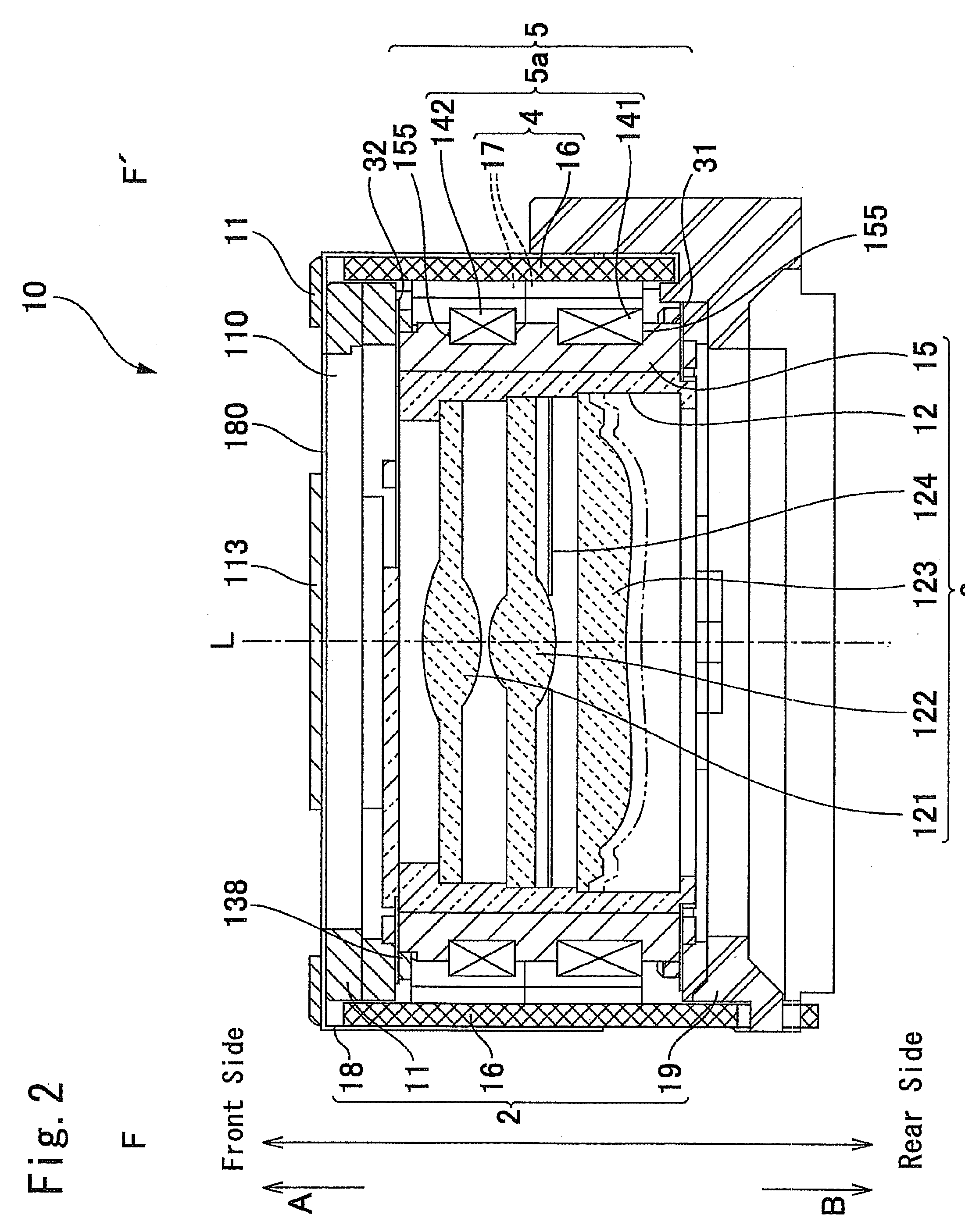
[0029]FIG. 1(A) is an outside appearance perspective view showing a lens drive device in accordance with an embodiment of the present invention which is viewed from obliquely upward, and FIG. 1(B) is its exploded perspective view. FIG. 2 is a cross-sectional view showing the lens drive device which is cut in the optical axis direction “L” at a position corresponding to the line of “F-F′” in FIG. 1(A).

[0030]In FIGS. 1(A) and 1(B) and FIG. 2, the lens drive device 10 in this ...


PUM


Abstract

A lens drive device may include a movable lens body provided with a lens, a support body which movably supports the movable lens body through a plate spring in an optical axis direction, and a magnetic drive mechanism for driving the movable lens body in the optical axis direction. The plate spring may include an outer side connecting part connected with the support body, an inner side connecting part connected with the movable lens body, and an arm part which is connected with the inner side connecting part and the outer side connecting part through an inner connecting portion and an outer connecting portion. The arm part may include a meandering part which comprises a plurality of extending parts which is extended in a radial direction is serially connected through inner side turning portions and outer side turning portions.

Description

CROSS REFERENCE TO RELATED APPLICATION[0001]The present invention claims priority under 35 U.S.C. §119 to Japanese Application No. 2006-355727 filed Dec. 28, 2006, which is incorporated herein by reference.FIELD OF THE INVENTION[0002]The present invention relates to a lens drive device in which a lens is driven in an optical axis direction to form an image of an object.BACKGROUND OF THE INVENTION[0003]In recent years, the use of a cellular phone having a camera has expanded. A portable device is provided with a lens drive device for driving and moving a lens in an optical axis direction. The lens drive device includes a movable lens body provided with a lens, a fixed body which movably supports the movable lens body in an optical axis direction through a plate spring, and a magnetic drive mechanism for driving the movable lens body in the optical axis direction. The plate spring includes an outer side connection part which is connected with the fixed body, an inner side connection p...

Claims


Application Information

Patent Timeline
Patent Type & Authority Applications(United States)
IPC IPC(8): G02B7/04
CPCG02B7/08G02B13/001H02K41/0356G03B2217/002G03B3/10
Inventor WADA, AKIHITOSATO, TSUNEO
Owner SANKYO SEIKI MFG CO LTD
Learn More