Ignition coil, and internal combustion engine ignition device

a technology of ignition device and ignition coil, which is applied in the direction of spark plugs, machines/engines, mechanical equipment, etc., can solve the problems of increased resistance value of wiring cables, increased loss of wiring cables, and inability to generate spark discharge normally, so as to reduce the accuracy of detection of ionic current and detect accurately

Inactive Publication Date: 2005-04-19
NGK SPARK PLUG CO LTD
View PDF7 Cites 12 Cited by
  • Summary
  • Abstract
  • Description
  • Claims
  • Application Information

AI Technical Summary

Benefits of technology

[0047]That is, in the internal combustion engine ignition system described above, the ignition coil in a state in which the protection metal pipe (plughole pipe) and the coil body portion are integrated with each other is directly connected to the spark plug without interposition of any wiring cable. For this reason, the distance between the terminal electrode electrically connected to the center electrode of the spark plug and the high voltage output terminal electrically connected to the secondary winding of the ignition coil is shortened so that contact characteristic between the terminal electrode and the high voltage output terminal is made good. Accordingly, lowering of accuracy in detection of the ionic current can be suppressed, so that the ionic current can be detected accurately.

Problems solved by technology

If lubricating oil is deposed on the spark plug, there is a possibility that the spark discharge cannot be generated normally because of influence of electrical leakage or the like.
When the ignition coil and the spark plug are connected to each other through the wiring cable such as a high tension cable or the like, there is however a problem that as the distance between the ignition coil and the spark plug increases, the resistance value of the wiring cable increases and the loss in the wiring cable increases because of the influence of external noise or the like.
When the loss in the wiring cable becomes high in this manner, energy for generating the ignition voltage is wastefully consumed by the wiring cable.
In some cases, there is fear that the spark discharge may not be generated because of shortage of the voltage value applied to the spark plug.

Method used


Image

  • Ignition coil, and internal combustion engine ignition device
  • Ignition coil, and internal combustion engine ignition device
  • Ignition coil, and internal combustion engine ignition device

Examples


first embodiment

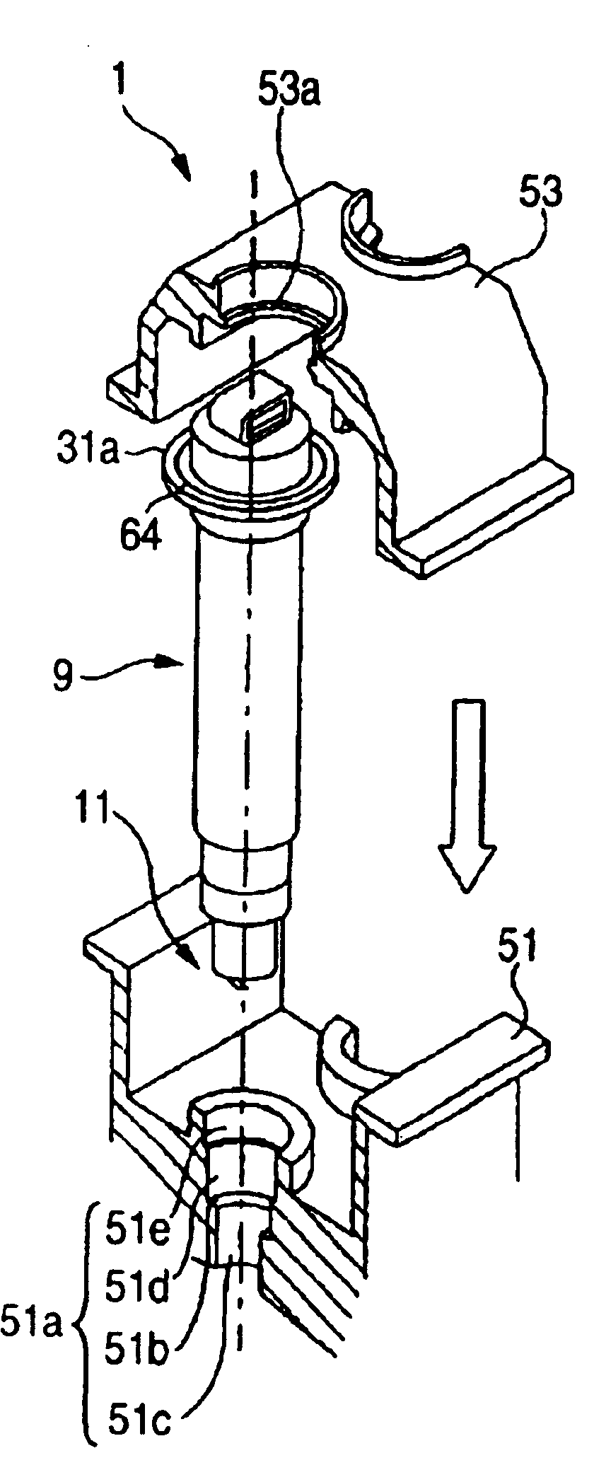
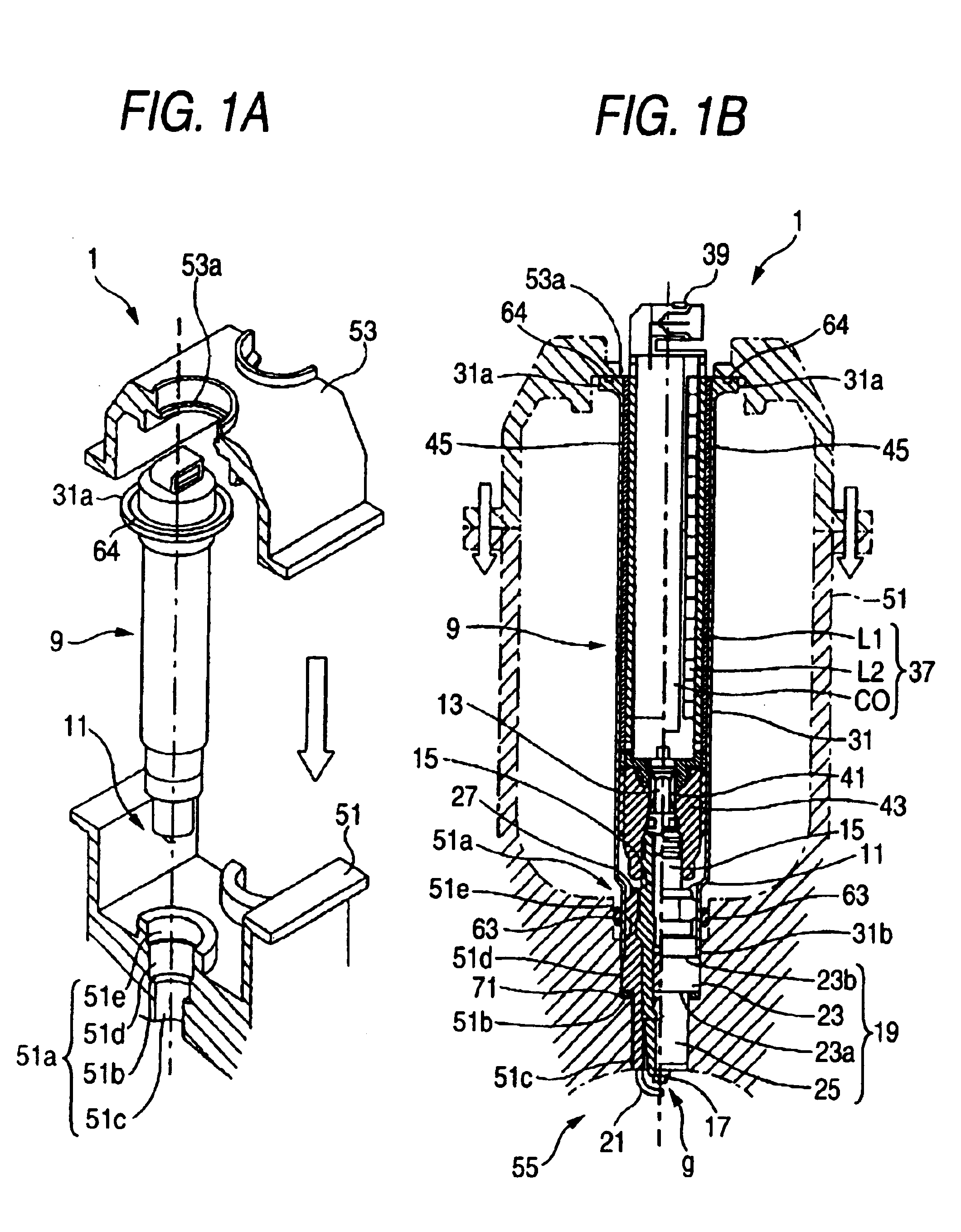
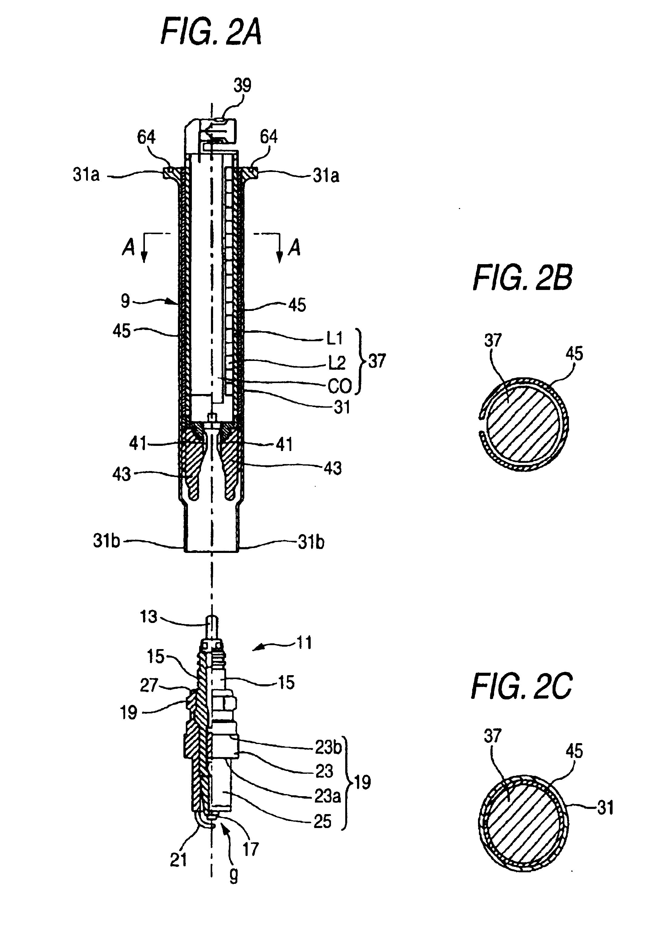
[0060]FIG. 1(a) is an explanatory view showing a state in which an ignition coil 9 provided in an internal combustion engine ignition system 1 is mounted in between a cylinder head 51 and a cylinder head cover 53 while the ignition coil 9 is directly connected to a spark plug 11. FIG. 1(b) is a sectional view of the cylinder head 51 and the cylinder head cover 53 after the ignition coil 9 and the spark plug 11 are mounted. FIG. 2(a) is a sectional view of the ignition coil 9 and the spark plug 11 in a state in which they are separated from each other.

[0061]Although the ignition coil 9 and the spark plug 11 are formed separately as shown in FIG. 2(a), the ignition coil 9 is directly connected to the spark plug 11 in a state in which the ignition coil 9 is mounted in the cylinder head 51 of the internal combustion engine as shown in FIG. 1(b). The ignition coil 9 and the spark plug 11 are disposed between the cylinder head 51 and the cylinder head cover 53 in a state in which the spa...

second embodiment

[0097]Accordingly, the internal combustion engine ignition system having the second ignition coil 9a described in the second embodiment can be achieved as an internal combustion engine ignition system in which misfire hardly occurs, so that a stable operating state of the internal combustion engine can be kept. In addition, because the number of man-hour for assembling can be made smaller than conventional, reduction in the cost of production of the internal combustion engine can be attained.

third embodiment

[0098]A third ignition coil 10 formed by using a third protection metal pipe 72 having a position regulating portion 83 for positioning the axial arrangement of the coil body portion 37 will be described below as a FIG. 4 shows an axial sectional view of the third ignition coil 10.

[0099]Incidentally, the third ignition coil 10 in the third embodiment is formed so that the third ignition coil 10 can be integrally coupled to the spark plug 11 in the first embodiment, and is formed so that the third ignition coil 10 can be disposed between the cylinder head 51 and the cylinder head cover 53. Incidentally, the structures of the spark plug 11, the cylinder head 51 and the cylinder head cover 53 are the same as those in the first embodiment and the description thereof will be omitted.

[0100]The third ignition coil 10 is formed to include a coil body portion 37, a third protection metal pipe 72, and an insulating member 43.

[0101]First, the coil body portion 37 is formed in the same manner ...


PUM

PropertyMeasurementUnit
pressureaaaaaaaaaa
angleaaaaaaaaaa
voltageaaaaaaaaaa

Abstract

An object of the present invention is to provide an ignition coil which has a structure to make it possible to connect the ignition coil to a spark plug directly and in which an installation space need not be changed largely when the ignition coil is mounted in a cylinder head, and an internal combustion engine ignition system having the ignition coil.
In the present invention, a protection metal pipe (31) of an ignition coil (9) is formed so that a rear end side portion of a spark plug (11) in the rear of a rear end surface (23b) of a collar portion (23) in a metal shell (19) can be received in the inside of the protection metal pipe (31) from a front end (31b). The ignition coil (9) has a structure in which the ignition coil (9) is directly connected to the spark plug (11). The protection metal pipe (31) of the ignition coil (9) is formed to serve also as a plughole pipe, so that the outer diameter of the protection metal pipe (31) can be enlarged up to the outer diameter of a conventional plughole pipe. As a result, a space for installing a coil body portion (37) can be secured largely in the inside of the protection metal pipe (31), so that the installation space need not be changed largely when the ignition coil is mounted in a cylinder head.

Description

TECHNICAL FIELD[0001]The present invention relates to an ignition coil for generating an ignition voltage to be applied to a spark plug attached to each cylinder of an internal combustion engine and an internal combustion engine ignition system having the ignition coil for generating a spark discharge to ignite an air-fuel mixture.BACKGROUND ART[0002]Conventionally, an internal combustion engine ignition system for igniting an air-fuel mixture in an internal combustion engine used as an automobile engine or the like is formed to include an ignition coil for generating an ignition voltage, and a spark plug for generating a spark discharge by the ignition voltage applied to the spark plug.[0003]Generally, the ignition coil includes a coil body portion having a primary winding, a secondary winding, and a coil core for magnetically coupling the two windings. The ignition coil is configured so that an ignition voltage is generated between opposite ends of the secondary winding by variati...

Claims


Application Information

Patent Timeline
Patent Type & Authority Patents(United States)
IPC IPC(8): F02P3/02H01T13/44H01T13/00H01T13/08F02P17/12F02P3/05H01F38/12
CPCF02P3/02H01T13/44H01T13/08H01F38/12F02P3/051F02P17/12H01F2038/122
Inventor FUMA, TOMOHIROINAGAKI, HIROSHISUZUKI, TAKAHIRO
Owner NGK SPARK PLUG CO LTD
Why Eureka
Try Eureka