Switching power source apparatus

a technology of power source apparatus and switch, which is applied in the direction of electric variable regulation, process and machine control, instruments, etc., can solve the problems of increasing the number of turns of secondary windings, increasing etc., to increase the number, increase the number of secondary windings, and increase the size and cost of third transformer

Inactive Publication Date: 2012-12-20
SANKEN ELECTRIC CO LTD
View PDF9 Cites 13 Cited by
  • Summary
  • Abstract
  • Description
  • Claims
  • Application Information

AI Technical Summary

Benefits of technology

[0016]The related art of Patent Document 2, however, applies a high voltage to the primary winding of the third transformer if an input DC voltage from a DC power source Vin is about, for example, 400 V. The third transformer, therefore, must be designed in consideration of saturation. To avoid saturation, the primary winding of the third transformer must have an increased number of turns. This results in increasing the numbers of turns of the secondary windings, thereby increasing the size and cost of the third transformer.

Problems solved by technology

This results in increasing the numbers of turns of the secondary windings, thereby increasing the size and cost of the third transformer.

Method used


Image

  • Switching power source apparatus
  • Switching power source apparatus
  • Switching power source apparatus

Examples


embodiment 1

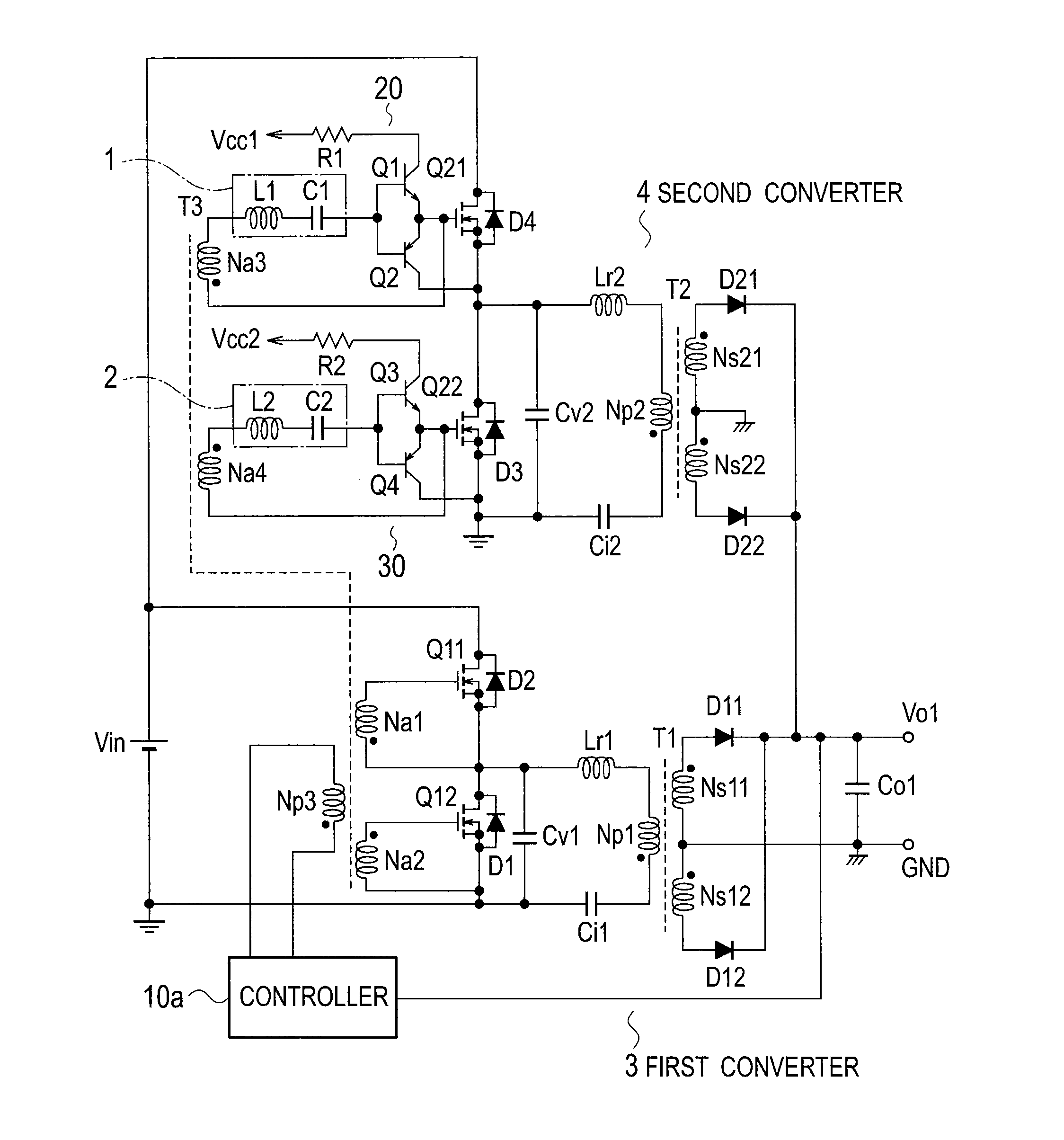
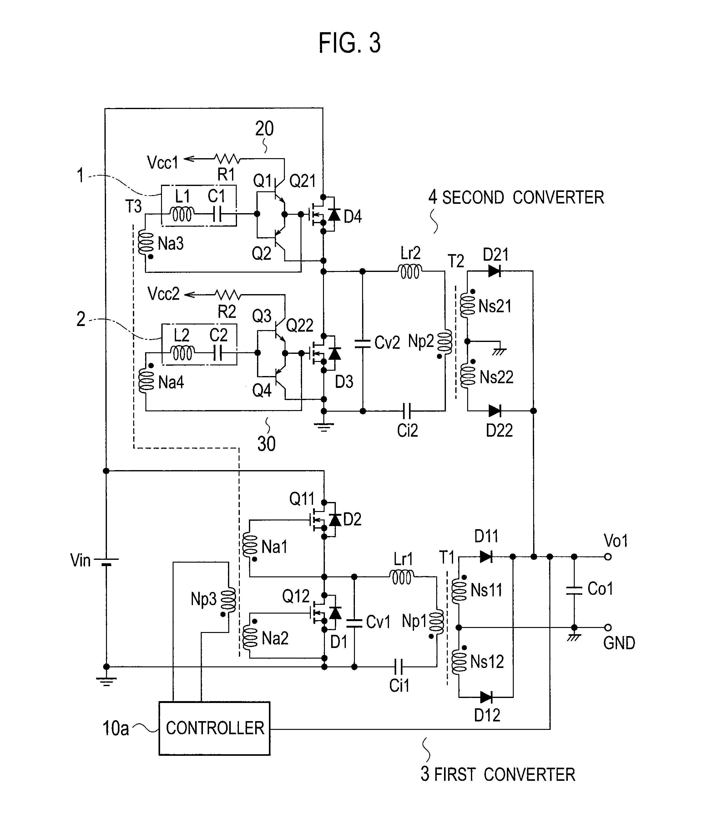
[0026]FIG. 3 is a circuit diagram illustrating a switching power source apparatus according to Embodiment 1 of the present invention. This switching power source apparatus includes a DC power source Vin, a first converter 3, a second converter 4, and an output smoothing capacitor Co1.

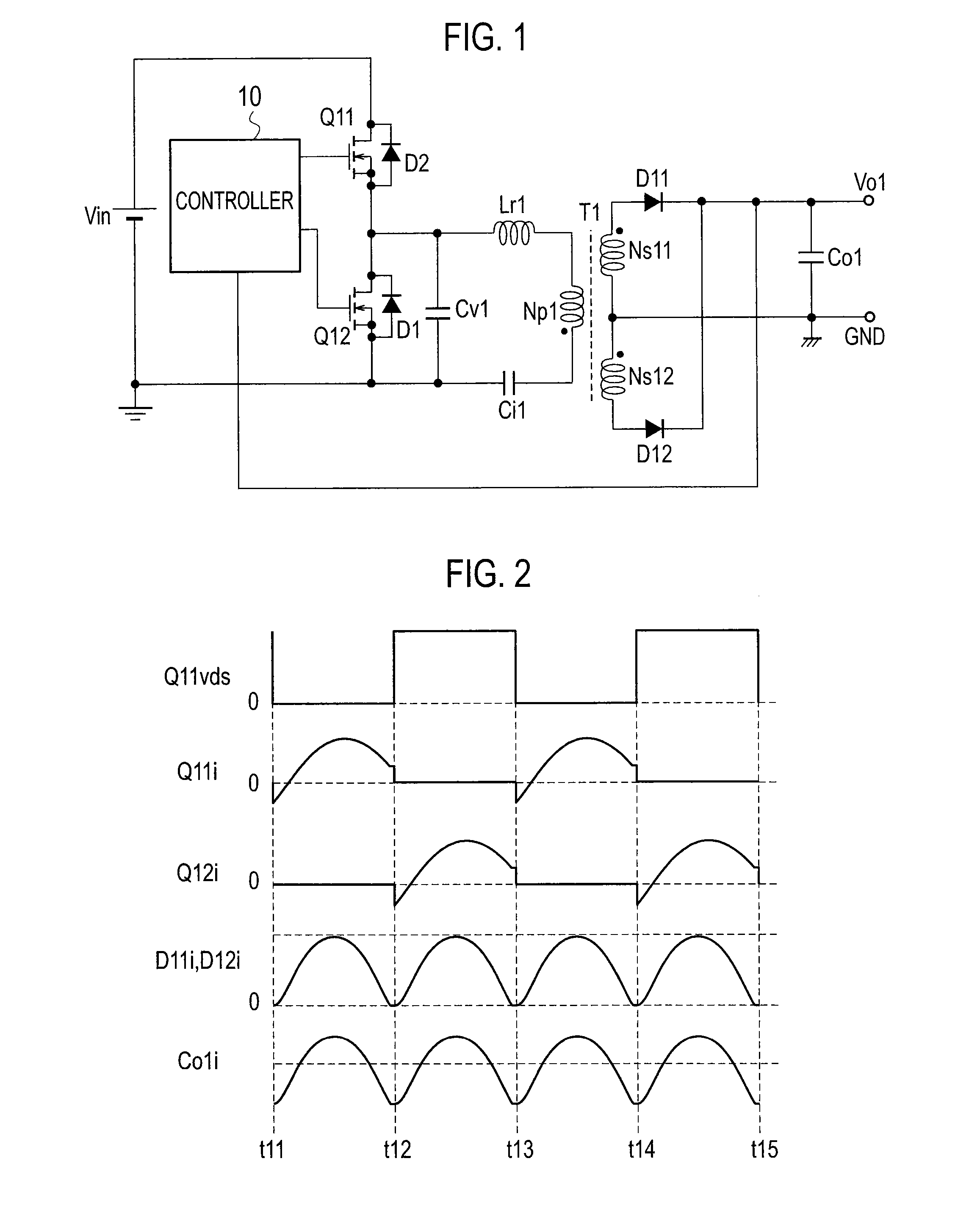
[0027]The first converter 3 is similar to the switching power source apparatus of the related art illustrated in FIG. 1 except for a pulse transformer T3 and a controller 10a, and therefore, overlapping explanations will be omitted.

[0028]The pulse transformer T3 (corresponding to the “third transformer” stipulated in the claims) has a primary winding Np3, a secondary winding Na1 (corresponding to the “third secondary winding” stipulated in the claims), a secondary winding Na2 (corresponding to the “fourth secondary winding” stipulated in the claims), a secondary winding Na3 (corresponding to the “first secondary winding” stipulated in the claims), and a secondary winding Na4 (corresponding to the “secon...

embodiment 2

[0056]FIG. 5 is a circuit diagram illustrating a switching power source apparatus according to Embodiment 2 of the present invention. Unlike Embodiment 1 of FIG. 3 that employs the single pulse transformer T3 having the primary winding Np3 and secondary windings Na1, Na2, Na3, and Na4, Embodiment 2 of FIG. 5 employs a pulse transformer T3a (corresponding to the “fourth transformer” stipulated in the claims) having a primary winding Np3 and secondary windings Na1 and Na2 and a pulse transformer T4 (corresponding to the “third transformer” stipulated in the claims) having a primary winding Np4 and secondary windings Na3 and Na4.

[0057]Both ends of the primary winding Np3 and both ends of the primary winding Np4 are connected to output terminals of a controller 10a. Connection relationships among the secondary windings Na1, Na2, Na3, and Na4 and switching elements Q11, Q12, Q21, and Q22 of Embodiment 2 are the same as those of Embodiment 1 illustrated in FIG. 3, and therefore, explanati...


PUM


Abstract

A switching power source apparatus has a pulse generator of a first pulse. A first resonant series circuit receives the first pulse signal and passes a current having a 90-degree phase delay with respect to the first pulse signal. The current of the first resonant series circuit turns on/off a switching element Q21. A second resonant series circuit receives the second pulse signal and passes a current having a 90-degree phase delay with respect to the second pulse signal. The current of the second resonant series circuit turns on/off a switching element Q22. The pulse generator has a third transformer T3 that has secondary windings to output the first and second pulse signals according to a voltage that is applied to the third transformer and is synchronized with drive signals for the switching elements Q11 and Q12.

Description

BACKGROUND OF THE INVENTION[0001]1. Field of the Invention[0002]The present invention relates to a switching power source apparatus that is simple and low cost.[0003]2. Description of Related Art[0004]FIG. 1 is a circuit diagram illustrating a switching power source apparatus according to a related art. This switching power source apparatus is a current resonant switching power source apparatus that receives a DC input voltage Vin generated by, for example, rectifying and smoothing a commercial AC voltage and supplied from a DC power source Vin. Both ends of the DC power source Vin are connected to a series circuit that includes first and second switching elements Q11 and Q12 are MOSFETs.[0005]Connected between the drain and source of the switching element Q12 (or Q11) are a voltage resonant capacitor Cv1 and a first resonant circuit that includes a resonant reactor Lr1, a primary winding Np1 of a transformer T1, and a current resonant capacitor Ci1. The resonant reactor Lr1 may be ...

Claims


Application Information

Patent Timeline
Patent Type & Authority Applications(United States)
IPC IPC(8): H02M3/335
CPCH02M3/337Y02B70/1433H02M2001/0058Y02B70/1491Y02B70/10H02M1/0058H02M3/33571H02M3/01
Inventor KYONO, YOICHI
Owner SANKEN ELECTRIC CO LTD
Why Eureka
Try Eureka