Nmr probe and nmr spectrometer

a spectrometer and nmr technology, applied in the field of nuclear magnetic resonance probes, can solve the problems of increasing the resistance the difficulty of obtaining the intrinsic high q factor of the antenna having low loss, and the increase of the resistive loss of the whole antenna circuit, so as to achieve small resistive loss, increase the number of turns of the antenna coil, and high sensitivity

Inactive Publication Date: 2008-05-15
HITACHI LTD
View PDF5 Cites 15 Cited by
  • Summary
  • Abstract
  • Description
  • Claims
  • Application Information

AI Technical Summary

Benefits of technology

[0015]Since the circuit according to the present invention can basically be composed of only two capacitors other than an antenna coil, the present invention can realize a tuning and matching of a resonance characteristic of an antenna circuit without reducing an intrinsic high Q factor of an antenna coil using a superconductor and having extremely small resistive loss. Further, the inductance of the antenna coil is divided by connecting a signal line in the antenna coil. As a result, the self-resonant frequency of the antenna coil is increased, and the number of turns of the antenna coil can be increased compared to the conventional antenna coil, whereby a signal can be detected with very high sensitivity.

Problems solved by technology

However, tuning and matching of the resonance characteristic is difficult in the cryogenic probe having extremely small resistance antenna, compared to the normal metal antenna at room temperature, so that it is difficult to obtain an intrinsic high Q factor of an antenna having low loss.
On the other hand, the circuit configuration in FIG. 1B entails a problem that the resistive loss increases due to the increase in the capacitance of the matching capacitor 44.
Therefore, when the component having large capacitance is used, the resistive loss of the whole antenna circuit increases, which reduces the Q factor.

Method used


Image

  • Nmr probe and nmr spectrometer
  • Nmr probe and nmr spectrometer
  • Nmr probe and nmr spectrometer

Examples


embodiment 1

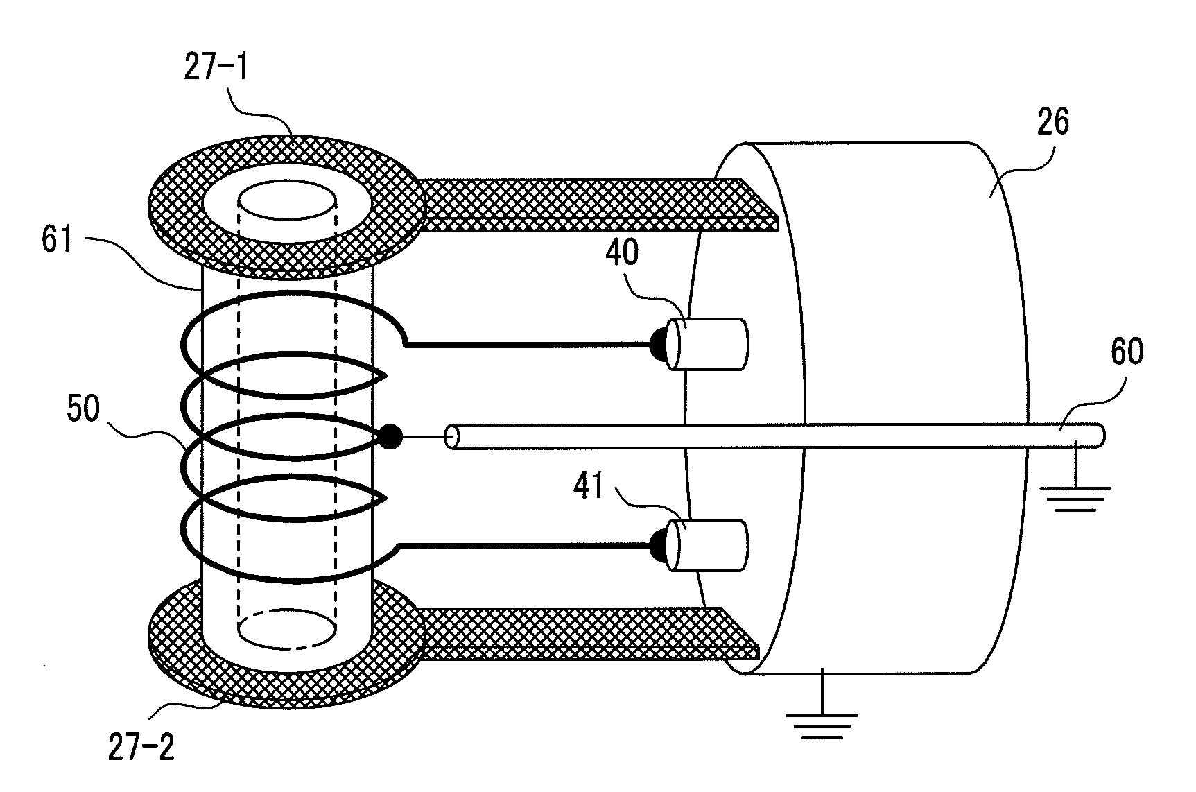
[0046]FIG. 5 is a perspective view showing an outline of main components of an NMR spectroscopy and their arrangement. A uniform magnetic field is produced along a centerline indicated by one-dot-chain line by superconducting magnets 10-1 and 10-2 divided into two. The produced magnetic field is indicated by an arrow B0. A sample tube 30 stores a sample 31 therein and is inserted from the direction (X-axis direction in the Figure) perpendicular to the static magnetic field. A cryogenic probe 20 having mounted thereto a solenoid-shaped probe antenna 25 for detecting a signal from the sample 31 is inserted from the direction same as the static magnetic field. The cryogenic probe 20 is composed of a probe antenna 25, a heat exchanger 22 at a leading end of a cryocooler serving as a cryogenic source, a leading-end stage 26 of the probe cooled by the heat exchanger, and a probe housing 23 that joint these components.

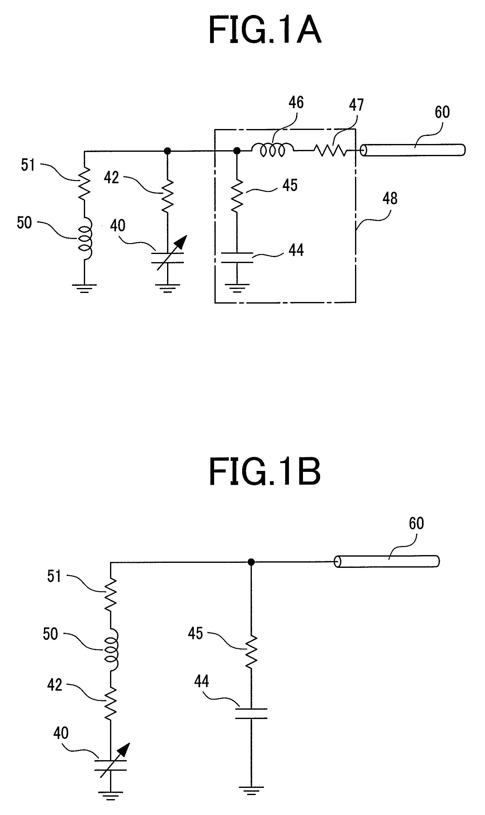
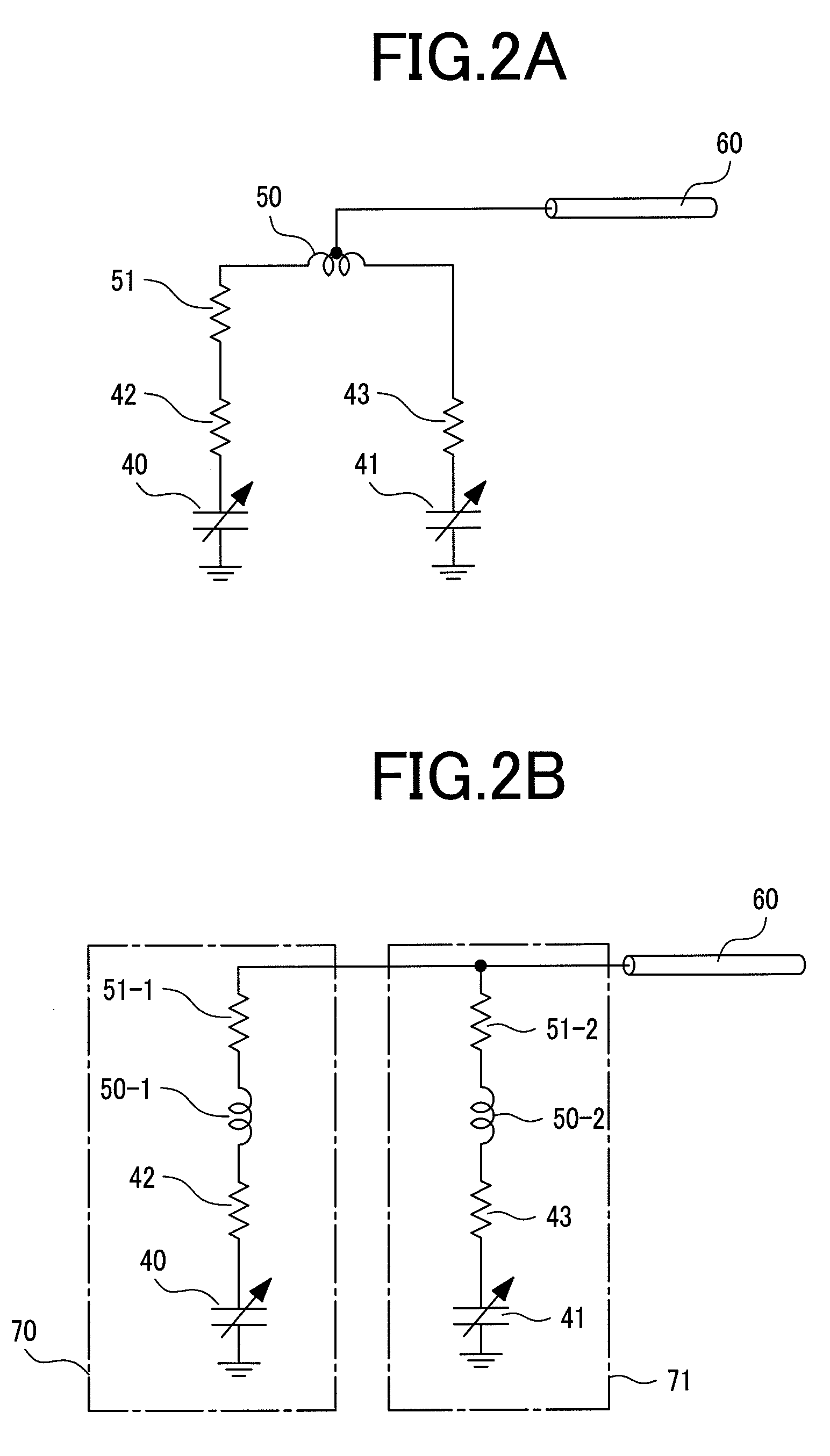
[0047]FIG. 6A is a schematic view showing an electrical connection of th...

embodiment 2

[0053]The embodiment 2 proposes an antenna using a superconducting thin film. The shape of the antenna is a solenoid type similar to that in the embodiment 1. FIG. 8A schematically shows the structure of the probe antenna in the embodiment 2. The antenna coil in the embodiment 2 is composed of superconducting thin film coils 81-1, 81-2, 81-3, and 81-4 formed on substrates 80-1, 80-2, 80-3, and 80-4, and normal metal tapes 82-1, 82-2, 82-3, 82-4, and 82-5 which electrically connect the coils. The signal line 60 is connected to the normal metal tape 82-3 that connects the second and third superconducting thin film coils. The capacitors 40 and 41 are connected to the normal metal tapes 82-1 and 82-5 serving as the end portions of the antenna coil.

[0054]FIG. 8B is a perspective view schematically showing the manner of mounting the solenoid-shaped probe antenna to a cryogenic probe 20. The substrates 80-1, 80-2, 80-3, and 80-4 having the superconducting thin film coils 81-1, 81-2, 81-3, ...

embodiment 3

[0061]The embodiment 3 proposes a solenoid-shaped antenna to which a superconducting thin film is applied like the embodiment 2. FIG. 9 is a perspective view schematically showing the structure of the probe antenna according to the embodiment 3. The basic structure of the probe antenna is the same as that in the embodiment 1. In the embodiment 3, the antenna coil is composed of a superconducting thin film 81 patterned onto the cylindrical bobbin 61 and normal metal tapes 82-1 and 82-2.

[0062]A method of manufacturing the probe antenna will be explained below. Firstly, an MgB2 superconducting thin film having a thickness of 300 nm is formed by a vapor deposition on the cylindrical bobbin 61 made of sapphire (Al2O3). Then, the formed superconducting thin film is mechanically grinded to form a helical pattern of the superconducting thin film having a width of 1 mm on the cylindrical bobbin 61. Thereafter, the normal metal tapes 82-1, 82-2, and 82-3 are connected to the generally middle ...


PUM


Abstract

A signal line is drawn from a generally middle point of the antenna coil, and a capacitance-variable capacitors are connected at both sides of the antenna coil. This structure realizes a circuit in which a series resonance circuit composed of an antenna coil and a capacitor and an another series resonance circuit composed of an another antenna coil and an another capacitor are connected in parallel to each other across the generally middle point of the antenna coil to which the signal line is connected. Through the control of the resonance frequencies of the series resonance circuits, the parallel resonance frequency of the whole antenna is tuned to a desired frequency, and the resonance characteristic in which the impedance is matched to a specific value, e.g., 50 Ω, can be achieved.

Description

CLAIM OF PRIORITY[0001]The present application claims priority from Japanese application JP 2006-304000 filed on Nov. 9, 2006, the content of which is hereby incorporated by reference into this application.BACKGROUND OF THE INVENTION[0002](1) Field of the Invention[0003]The present invention relates to a nuclear magnetic resonance probe (hereinafter referred to as an “NMR probe”) and an NMR spectrometer using the same, and more particularly to an NMR spectrometer which is characterized by a circuit configuration and mounting configuration of a probe antenna for transmitting radio frequency signals at a prescribed resonance frequency to a sample placed in a static magnetic field and / or receiving free induction decay (FID) signals.[0004](2) Description of the Related Arts[0005]Nuclear magnetic resonance (NMR) spectroscopy, by which one can get atomic level information on matter, is an excellent method of analyzing the structure of a compound. The basic principle of analysis by this me...

Claims


Application Information

Patent Timeline
Patent Type & Authority Applications(United States)
IPC IPC(8): G01R33/32
CPCG01R33/30G01R33/34023G01R33/34046G01R33/3635G01R33/34069G01R33/34092G01R33/3628G01R33/34053
Inventor YAMAMOTO, HIROYUKININOMIYA, TAKANORISAITOH, KAZUO
Owner HITACHI LTD
Why Eureka
Try Eureka