Power feed system for vehicle

a technology for feeding systems and vehicles, applied in emergency protective circuit arrangements, doors, transportation and packaging, etc., can solve problems such as defective contact between equipment and power lines, and the operation cannot be activated upon operation request, and achieve excellent effect, easy identification, and excellent effect.

Inactive Publication Date: 2009-01-15
FURUKAWA ELECTRIC CO LTD
View PDF12 Cites 53 Cited by
  • Summary
  • Abstract
  • Description
  • Claims
  • Application Information

AI Technical Summary

Benefits of technology

[0057]According to this invention, when an abnormal current is detected by an abnormal current detection portion of any node at a normal time, a switching portion of the node is switched to power feed to a detection signal generation portion of the node from the power feed to a load. As a result, since a predetermined output signal is provided to a driver via a diagnostic signal line from the detection signal generation portion, it has an excellent effect that the driver can know occurrence of the abnormality and the location of abnormality occurrence at once. Also, by using a common diagnostic signal line, it can be realized without increasing a load of a multiplex transmission line and a multiplex transmitting device, and moreover, it has an excellent effect that even if an abnormality occurs at the multiplex transmission line, the power feed state to each node can be checked.
[0058]Moreover, according to the power feed system for a vehicle of this invention, since the switching portion of the node is connected to the detection signal generation portion side in case of non-operation of the load, it has an excellent effect that normal power feed to the node can be checked even if the load is not operating.
[0059]Moreover, according to the power feed system for a vehicle of this invention, by setting the size of a resistor of the detection signal generation portion of each node to a different value specific to each node, it has an excellent effect that a node where an abnormality occurs can be determined based on a signal transmitted from the detection signal generation portion via the diagnostic signal line at abnormality.
[0060]Moreover, according to the power feed system for a vehicle of this invention, by setting the size of a resistor of the detection signal generation portion of each node so that a signal transmitted from the detection signal generation portion of each node via the diagnostic signal line becomes a predetermined value, it has an excellent effect that an abnormal node can be easily identified at occurrence of an abnormality.
[0061]Moreover, according to this invention, by connecting the detection signal generation portion of each node to the multiplex transmission line so that an output signal from the detection signal generation portion is transmitted via the multiplex transmission line, it has an excellent effect that a common diagnostic signal line is not needed any more and not only costs are reduced but a wiring volume is also reduced.
[0062]Moreover, according to this invention, by adding a display portion for displaying an output signal from the detection signal generation portion of each node, it has an excellent effect that a display method by which the operation / non-operation state of a load of each node and connection state of the power line and each node can be easily recognized can be provided to a driver.

Problems solved by technology

As nonconformity found in the load of the electric devices, not only such a case that an abnormal current is generated during operation of a normal load but also many nonconformities are seen that even during non-operation, operation can not be activated upon operation request due to the reason as insufficient contact between the load of the electric devices and a power line.
However, a true cause is often a defective contact between the equipment and the power line rather than nonconformity of the equipment.

Method used


Image

  • Power feed system for vehicle
  • Power feed system for vehicle
  • Power feed system for vehicle

Examples


Embodiment Construction

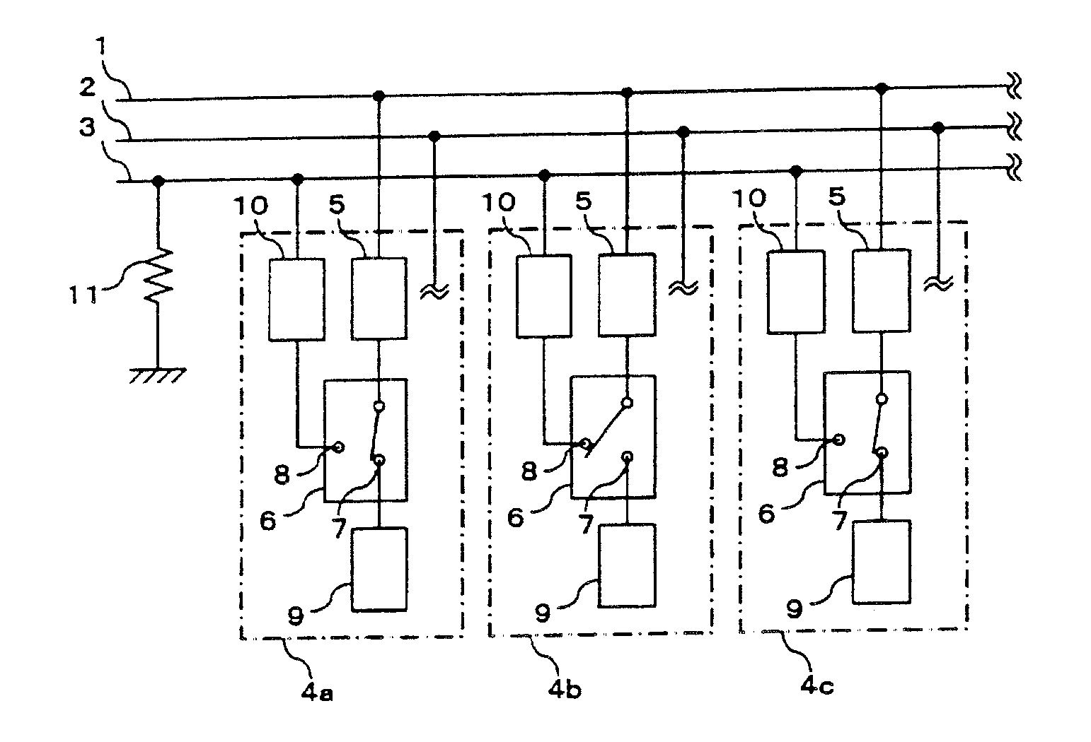
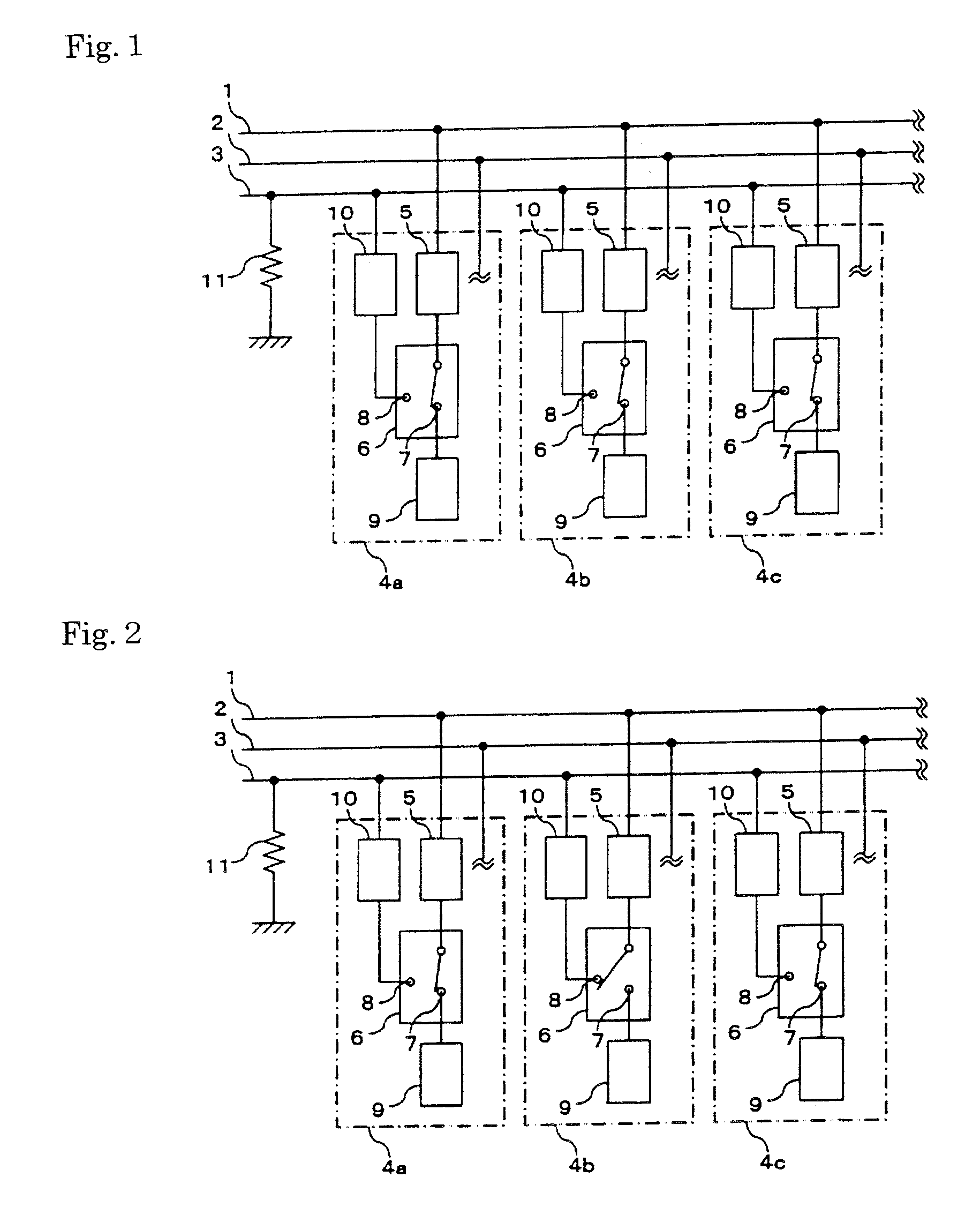
[0179]Embodiments of a power feed system for a vehicle according to the present invention will be described referring to the accompanying drawings.

[0180]A first mode of a power feed system for a vehicle of the present invention is a power feed system for a vehicle provided with a plurality of nodes provided with a load control portion for controlling an electric load disposed at each portion of a vehicle, respectively, a power line for supplying power to each node, and a multiplex transmission line connecting each node to each other, comprising an abnormal current detection portion disposed in a line for receiving power feed from the power line at each node for detecting abnormality of a load current, a detection signal generation portion which starts to receive power when abnormality is detected at the abnormal current detection portion and sends a weak current as an output signal, a diagnostic signal line in common to each node, connected to the detection signal generation portion...


PUM


Abstract

A power feed system for a vehicle provided with a plurality of nodes (4a, 4b, 4c) provided with a load control portion (9) for controlling an electric load disposed at each portion of a vehicle, respectively, a power line (1) for supplying power to each node, and a multiplex transmission line (2) connecting each node to each other, comprising an abnormal current detection portion (5) disposed in a line for receiving power feed from the power line at each node for detecting abnormality of a load current, a detection signal generation portion (10) that starts to receive power when abnormality is detected at the abnormal current detection portion and sends a weak current as an output signal, a diagnostic signal line (3) in common to each node, connected to the detection signal generation portion for transmitting the signal from the detection signal generation portion, and a switching portion (6) for switching the power feed from the power line to the load control portion or the detection signal generation portion.

Description

TECHNICAL FIELD[0001]The present invention relates to a power feed system for a vehicle which supplies power such as a power supply to a control system such as a distributed control system for controlling a load of various electric devices mounted on a vehicle.BACKGROUND ART[0002]A load of the electric devices of a vehicle has been increased and a power supply system and a signal system for electronic control of a main machine and an auxiliary machine have been increased and a large quantity of electric equipment are mounted exemplified in a change of instruments of a front panel to electronic display method. With that trend, increase of the power supply system and the signal system has become a big problem, and standardization and rationalization of the power supply system and the signal system have been promoted in order to ensure their reliability. As an example, a CAN (controller area network) system is applied to a backbone system to a signal system, while an in-vehicle LAN to ...

Claims


Application Information

Patent Timeline
Patent Type & Authority Applications(United States)
IPC IPC(8): H02H3/04B60J5/00B60R16/02B60R16/023H02J1/08
CPCH02J1/08B60R16/023
Inventor HARA, SHOJIICHII, EIJITAKAHASHI, HIROAKIABE, KEN
Owner FURUKAWA ELECTRIC CO LTD
Why Eureka
Try Eureka