Incoupling structure for lighting applications

Active Publication Date: 2009-01-15
MODILIS HLDG LLC
View PDF3 Cites 101 Cited by
  • Summary
  • Abstract
  • Description
  • Claims
  • Application Information

AI Technical Summary

Benefits of technology

[0026]The utility of embodiments of present invention may arise from a plurality of issues depending on each scenario. The incoupling structure may generally function as a homogenizer of light distribution. The incoupling structure may especially be configured so as to efficiently collimate and/or uniform the light provided to the target entity such as a lightguide. Alternatively, the incoupling structure may be utilized to couple light directly into target environment, e.g. surrounding space, without further entities such as lightguides in between.
[0027]Many solutions typicall

Problems solved by technology

Either the arrangements have been rather bulky and thus unsuitable for micro-scale applications wherein size restrictions for positioning the lightguide, light source and associated elements are considerable, or

Method used


Image

  • Incoupling structure for lighting applications
  • Incoupling structure for lighting applications
  • Incoupling structure for lighting applications

Examples


Example

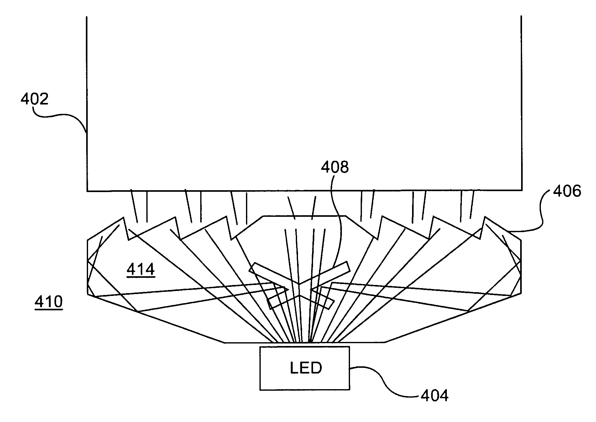
[0068]Generally, a light source may be connected directly to a lightguide element and thus introduce light thereto without additional means. Alternatively, the lightguide may be arranged with one or more incoupling structures. The incoupling structure may include a wedge including specular reflectors on at least one of a top and bottom surface, an elliptical light pipe, a focusing lens and / or a bundle of split optic fibers. On the other hand, the light source and the incoupling structure may form a unitary structure. When the lightguide element includes multiple lightguide layers, incoupling may vary among the layers.

[0069]FIG. 4a illustrates one embodiment of the incoupling structure 410 in accordance with the present invention. The utilized light source 404 may include a LED, such as NICHIA NSSW020BT, for example. The target entity is in this case a lightguide 402, which may be a substantially planar lightguide and have a thickness of e.g. about 0.5 mm and illumination area width ...


PUM


Abstract

Light incoupling structures for lighting applications, such as lightguides. The incoupling structures include an optically substantially transparent medium for transporting light emitted by a light source and an optical element including at least one hole in the medium for coupling light together with optional further optical elements. A lighting element includes a light source with related integrated optics.

Description

CROSS-REFERENCE TO RELATED APPLICATIONS[0001]This application claims priority to U.S. provisional patent application 60 / 877,648 filed 29 Dec. 2006.FIELD OF THE INVENTION[0002]Generally the invention relates to optics. In particular, the invention pertains to incoupling light from a light source to target environment and target entities via optional intermediate elements such as lightguides.BACKGROUND[0003]Lightguides are waveguides that are typically used for guiding light emitted by light sources in various lighting solutions. The lightguides can be used for display lighting (e.g. back-lighting, front-lighting), keypad, keyboard and / or button lighting, interior lighting, and exterior lighting, among other applications. Conventional lightguides that are considered as thin may have a thickness of about 0.8 to about 1.0 mm and include micro-optical structures for incoupling light thereto and / or outcoupling light therefrom.[0004]FIG. 1 illustrates a side view of an embodiment of a plan...

Claims


Application Information

Patent Timeline
IPC IPC(8): G02B3/08F21V1/12F21S8/00
CPCG02B6/0016G02B6/003G02B6/0028G02B6/0018G02B6/00G02B6/0001
Inventor RINKO, KARI
Owner MODILIS HLDG LLC
Why Eureka
Try Eureka