Packet transmission method and device

a technology of packet transmission and transmission method, applied in the field of packet transmission method and device, can solve the problems of increasing heat generation, increasing and a large amount of data processing recently required, and achieve the effect of simplifying circuit arrangement and suppressing power consumption and heat generation of devices

Inactive Publication Date: 2009-01-15
FUJITSU LTD
View PDF2 Cites 12 Cited by
  • Summary
  • Abstract
  • Description
  • Claims
  • Application Information

AI Technical Summary

Benefits of technology

[0199]It is accordingly an object of the present invention to provide a packet transmission method and device, for solving the above problem, which can suppress a power consumption and a heat generation of the device due to reduction of circuit scale by excluding a packet processing delay and simplifying the circuit arrangement.
[0203]Accordingly, without using FIFO or the like storing packets at the latter stage of the packet buffer, a packet transmission can be performed by address, thereby preventing a processing time delay.
[0210]In this embodiment, without using a FIFO storing packets at the latter stage of the packet buffer, a real transmission rate adjustment for each port can be performed with a small-scale address FIFO or the like newly provided before reading a frame from the packet buffer, so that it becomes possible to make a significant scale reduction, down sizing, and power reduction.
[0211]Also, upon issuing or releasing addresses, and managing the address chain (connecting order) within a frame, a free address managing memory monitoring the issuance or release of addresses and an address chain managing memory managing the address chain within a frame can be integrated in the same shared managing memory, so that the storage capacity and power consumption can be reduced.

Problems solved by technology

Meanwhile, a device processing a large quantity of data has been recently required as the number of subscriber increases.
Therefore, in case a packet FIFO is provided by physical port as described above, it has been disadvantageous that a time delay of data processing due to packets remaining in the packet FIFO, incurring an increased power consumption and heat generation due to increase of a circuit scale because of the free address managing memory and the address chain managing memory being separately used, as well as an increased heat generation due to downsizing.

Method used


Image

  • Packet transmission method and device
  • Packet transmission method and device
  • Packet transmission method and device

Examples


Embodiment Construction

Arrangement of LIU Card Embodiment: FIGS. 1 and 2

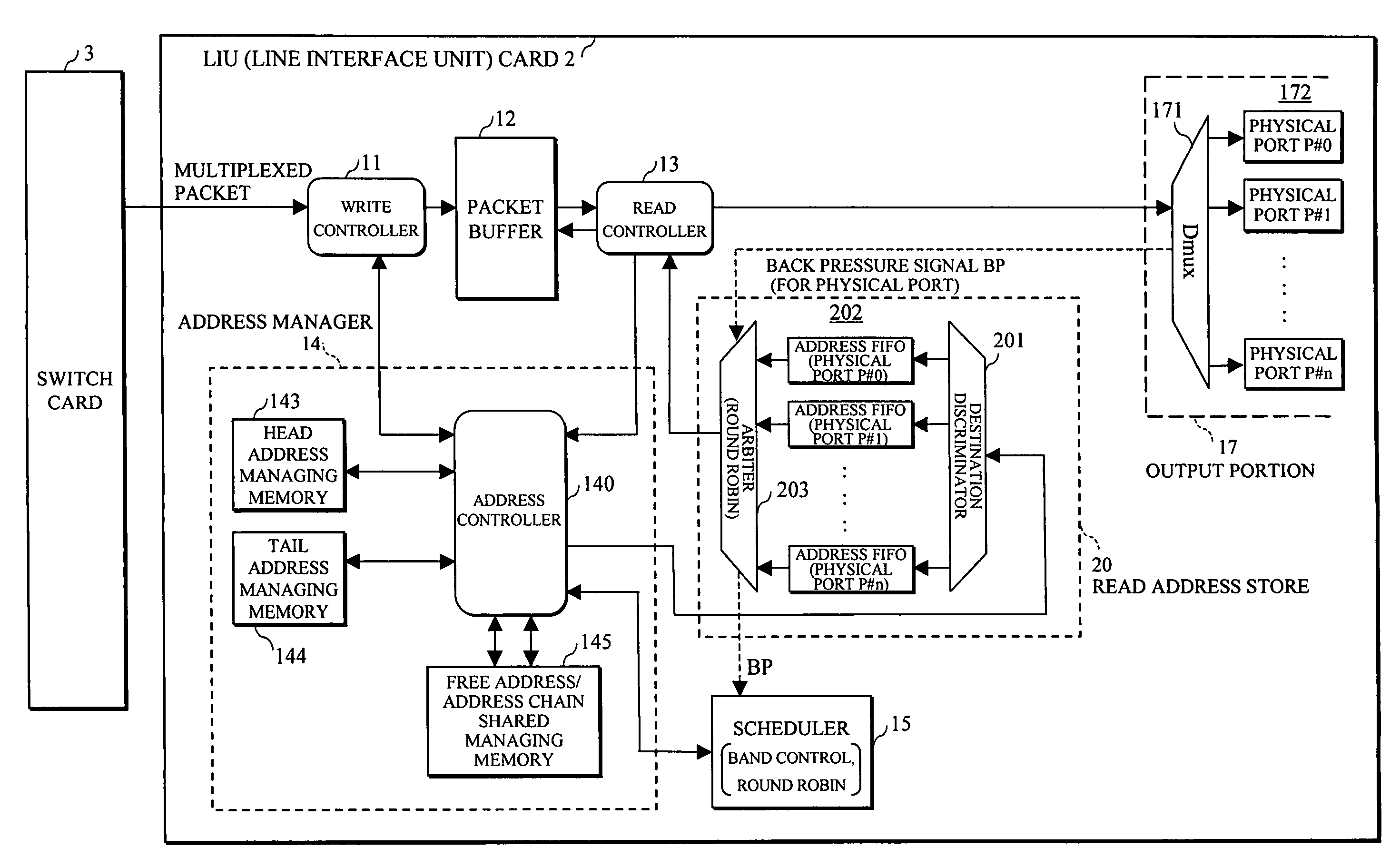
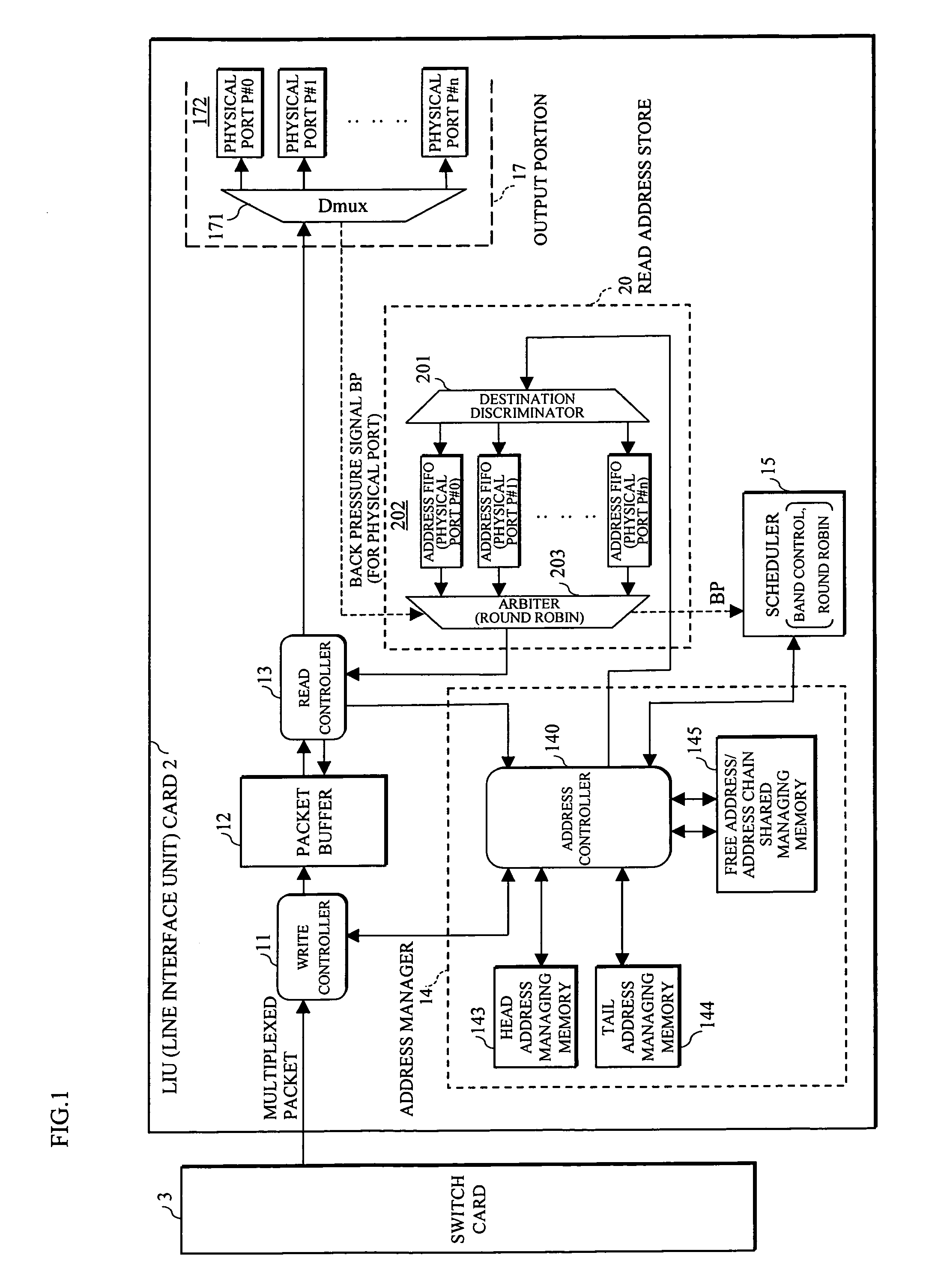
[0254]FIG. 1 shows an arrangement of an LIU card 2 used in an embodiment of a packet transmission method and device. This arrangement is adapted to make an actual transmission rate adjustment for each physical port with a newly provided small-scale address FIFO before reading a packets from a packet buffer, without using a packet FIFO by physical port used for an output rate control.

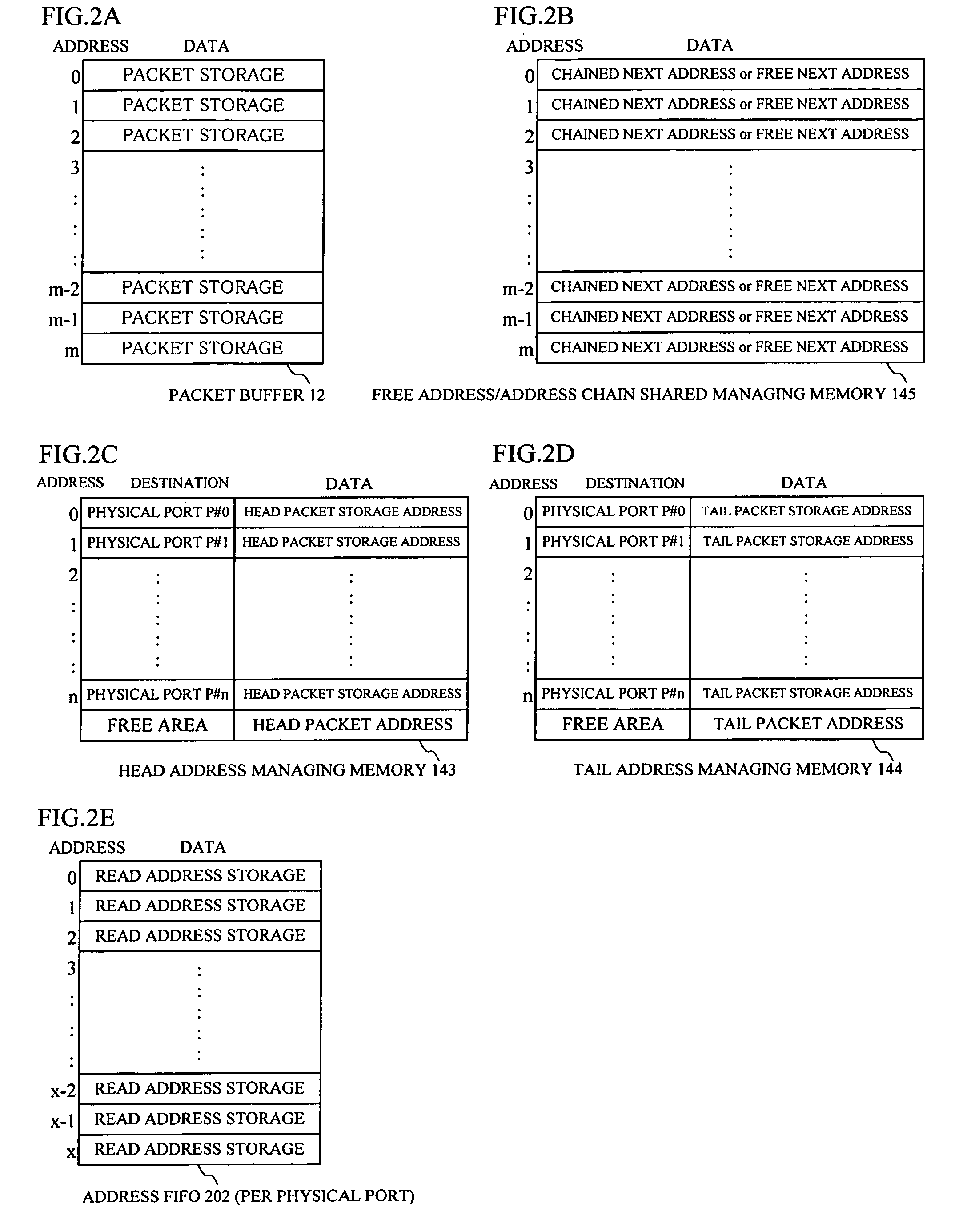
[0255]For this purpose, this embodiment is different from the prior art arrangement shown in FIG. 21 in that the read controller 13 is directly connected to the output portion 17, the packet controller is replaced by a read address store 20 which is connected between the address controller 140 and the read controller 13, and the address manager 14 uses a free address / address chain-shared managing memory 145 (hereinafter, occasionally referred to simply as a shared managing memory 145) having commoditized the free address managing memory and the address cha...


PUM


Abstract

In a packet transmission method and device, when a received packet is written in a packet buffer, an address of the packet buffer is stored as a read address for each destination corresponding to a physical port and storing information of the received packet. The read address of a destination designated by the received packet information is read and saved when the received packet is read out of the packet buffer in accordance with a scheduling control. Then, the saved read address is taken out in accordance with an arbitration control and a received packet corresponding to the saved read address is read from the packet buffer.

Description

CROSS-REFERENCE TO RELATED APPLICATIONS[0001]This application is related to and claims priority to Japanese Patent Application No. 2007-183532, filed on Jul. 12, 2007, in the Japan Patent Office, and incorporated by reference.BACKGROUND[0002]1. Field[0003]The present invention relates to a packet transmission method and device, an in particular to a packet transmission (transfer) method and device for reading a packet such as an Ethernet (trademark) frame from a packet buffer having temporarily stored the packet for each destination in a scheduling control in the field of art providing a function such as QoS (Quality of Service) control, priority control, bandwidth control, etc. in an layer 2 (L2) switch device used in an IP network.[0004]2. Description of the Related Art[0005]In a prior art device for switching a packet between networks or within a network, a scheduler (scheduling portion), an input FIFO and output FIFO have been employed to achieve a QoS control, priority control,...

Claims


Application Information

Patent Timeline
Patent Type & Authority Applications(United States)
IPC IPC(8): H04L12/56H04L12/28H04L47/22H04L49/901
CPCH04L47/6225H04L49/9063H04L49/901H04L49/90
Inventor MATSUO, TAMOTSUFUKUNAGA, KENJIKOJI, TOSHIHIROOGAWA, MASAYUKIURANO, HIROSHI
Owner FUJITSU LTD
Why Eureka
Try Eureka