
Well jet device and the operating method thereof

a jet device and well technology, applied in the field of pumping units, can solve the problems of narrow application field and inability to fully utilize the capabilities of the jet device, and achieve the effect of increasing the reliability of information and reducing the time spen

Inactive Publication Date: 2009-01-15
KHOMYNETS ZINOVIY DMITRIEVICH
View PDF3 Cites 15 Cited by
  • Summary
  • Abstract
  • Description
  • Claims
  • Application Information

AI Technical Summary

Benefits of technology

"The invention is a well jet device that can expand its capabilities and improve the efficiency of conducting various studies and operations in a well. It includes a supporting sleeve that is spring-loaded against the body of the device, which allows for the separation of the inner cavity from the surrounding space while carrying out certain process operations. The device also has additional sealing elements and a bypass channel for supplying active fluid to the nozzle of the jet pump. The invention can lower the time and cost of conducting studies and repairs in a well, and it can also provide more reliable information about the physical properties of the producing formation. The device can also be used for pumping cement and carrying out water-isolation works."

Problems solved by technology

However, this device provides that a working fluid is supplied to the nozzle of the jet device along the pipe string, which, in a number of cases, narrows its field of application.
But this well jet device does not enable using its capabilities in full, which is connected with its design limitations becoming obvious when studying producing formations in a well or when pumping acid solutions and hydrofracturing liquids into a formation.

Method used


Image

  • Well jet device and the operating method thereof
  • Well jet device and the operating method thereof
  • Well jet device and the operating method thereof

Examples


Embodiment Construction

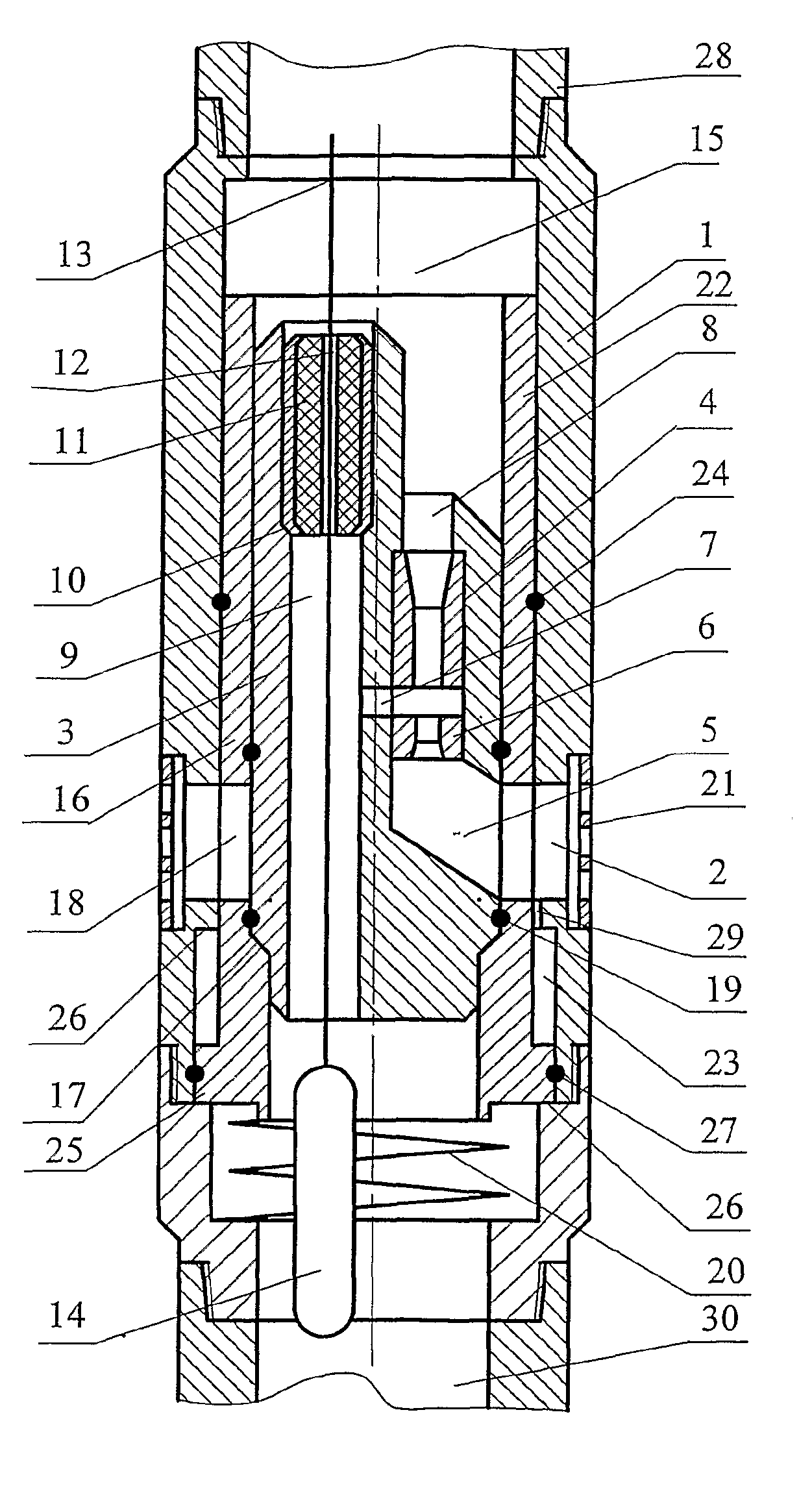
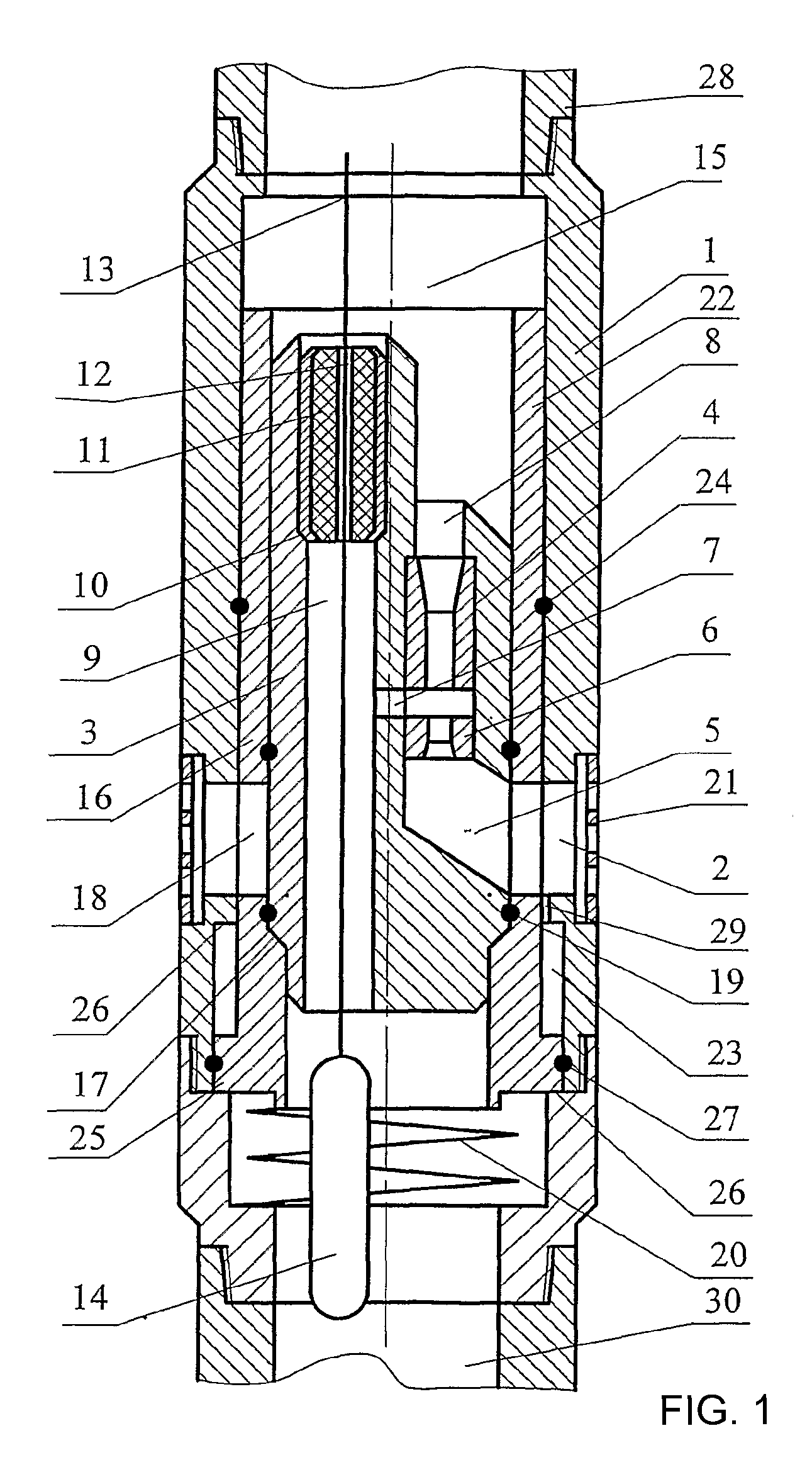
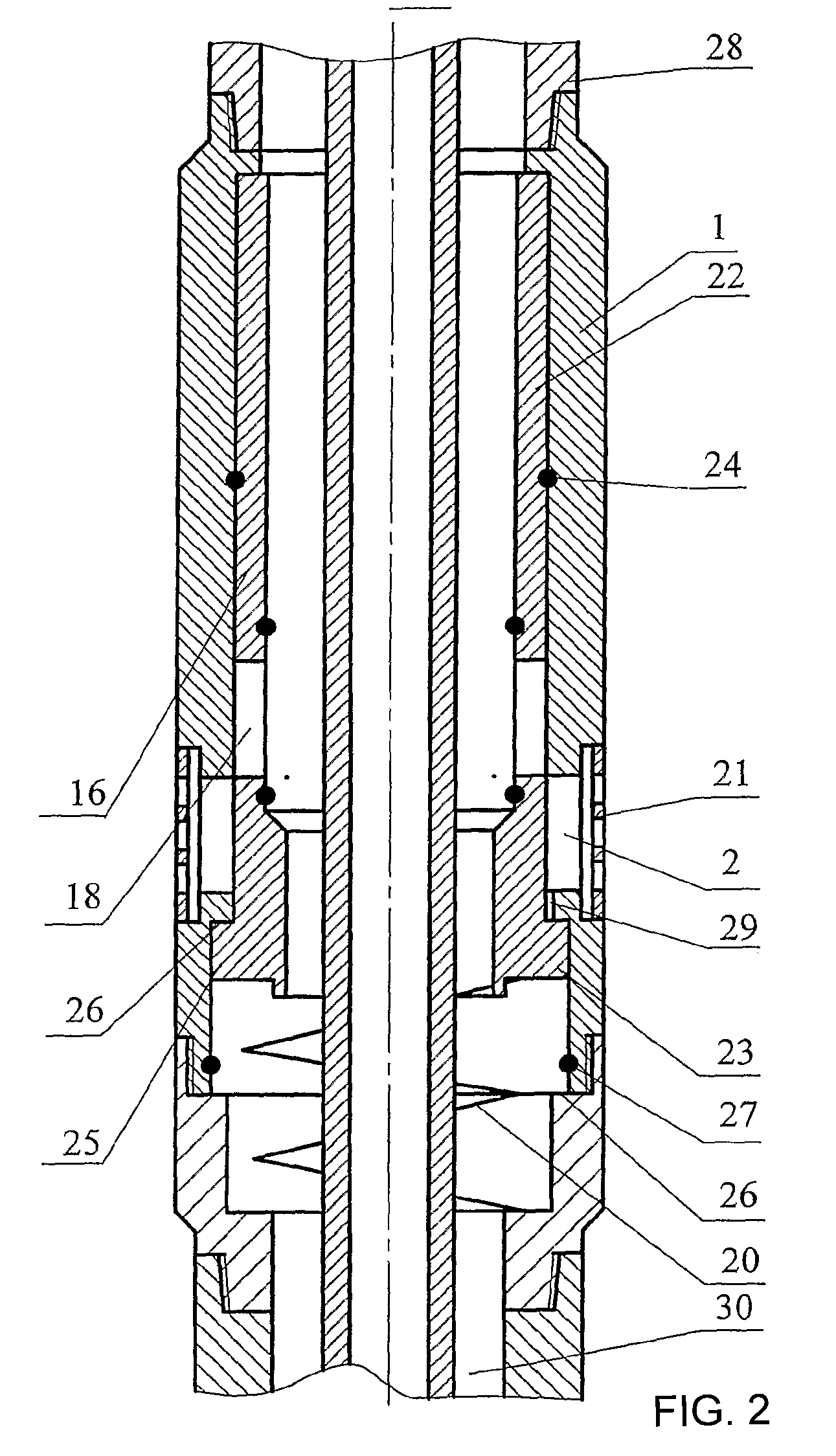
[0020]The claimed well jet device comprises a body 1 provided with bypass windows 2 and an insert 3 provided with a jet pump 4 and a through channel 9. Further, the insert 3 is provided with a channel 5 for supplying an active fluid to the nozzle 6 of the jet pump 4, a channel 7 for supplying a pumped out fluid to the jet pump, said channel 7 being connected to the through channel 9, and an output channel 8. A mounting seat 10 is made above the channel 7 for supplying a pumped out fluid in the through channel 9 for the purpose of arranging a sealing unit 11 in the through channel 9. The sealing unit 11 is provided with an axial channel 12 for passing through it and the through channel 9 a cable or wire 13 for the purpose of arranging borehole instruments and equipment 14 on it and below the jet pump 4 in a well with the possibility of moving them along the well borehole when the jet pump 4 is or is not operated. The output channel 8 communicates with the inner cavity 15 of the body ...


PUM


Abstract

A well jet device for testing oil-gas wells comprises a body provided with bypass windows and an insert provided with a jet pump. The insert has channels and a mounting seat embodied therein, carrying a sealing unit with a channel for a cable and well instruments fixed thereto. An output channel communicates with an upstream cavity. A supporting sleeve, provided with bypass openings embodied in the wall of the sleeve and with a flange arranged in the lower part thereof, axially movable and spring-loaded with respect to the body, is arranged therein. A recess used for limiting the displacement of the sleeve flange and connected to the bypass windows is formed thereunder. In the lower position of the sleeve, channel for supplying active medium is linked with surrounding space through the bypass openings and windows, whereas in the top position thereof the windows are closed by the sleeve wall.

Description

FIELD OF THE INVENTION[0001]This invention relates to pump equipment, in particular to well pumping units for testing oil and gas wells.PRIOR ART[0002]A well jet device is known that comprises a jet pump installed on the production string in the well and a geophysical instrument arranged in the production string below the jet pump (RU 2059891 C1).[0003]The same patent teaches a method of operating a well jet device, comprising feeding an active fluid through a pipe string to the nozzle of a jet pump, wherein said active fluid, while exiting the pump entraps a pumped liquid fluid to a mixing chamber, from the latter a fluid mixture is supplied to a diffuser where kinematic energy of the flow is partially transformed to its potential energy, and from the diffuser said fluid mixture is supplied along the annular space of the pipe string to a consumer, the physical parameters of the pumped out fluid and the producing formation (pressure, density, gas saturation, solid phase content, tem...

Claims


Application Information

Patent Timeline
Patent Type & Authority Applications(United States)
IPC IPC(8): F04F5/54E21B47/00E21B43/00E21B49/08
CPCF04F5/464E21B43/124E21B43/129
Inventor KHOMYNETS, ZINOVIY DMITRIEVICH
Owner KHOMYNETS ZINOVIY DMITRIEVICH
Learn More