Cell Laminate and Fuel Cell Provided with the Same

Active Publication Date: 2009-01-15
TOYOTA JIDOSHA KK
View PDF2 Cites 6 Cited by
  • Summary
  • Abstract
  • Description
  • Claims
  • Application Information

AI Technical Summary

Benefits of technology

[0015]Moreover, in the cell laminate, it is further preferable that frame-like member is provided with separator deformation inhibiting projections which project toward the recessed back surface of the deformation inhibiting region formed on the separator to suppress the deformation of the separator at the deformation inhibiting region or nearby. In consequence, when, for example, an adhesive is interposed between the separator and the frame-like member, the thickness (projection amount) of an adhesive layer (the layer constituted of an adhesive) can be decreased as much as the thickness (projection amount) of the projections for inhibiting the separator deformation. If the rigidity of the frame-like member is higher than that of the adhesive layer, the rigidity of the portion for backing up the back surface of the deformation inhibiting region can be increased to suppress the deformation of the corresponding portion or nearby.
[0016]Furthermore, according to the present invention, there is provided a cell laminate in which separators each holding a membrane-electrode assembly therebetween are laminated, wherein between adjacent separators, there is formed either a power generation region where the membrane-electrode assembly and a frame-like member which holds at least a part of this membrane-el

Problems solved by technology

However, in the actual situation, there has sufficiently not been investigated a backup structure capable of effectively inhibiting the deformation of a separator having a structure w

Method used


Image

  • Cell Laminate and Fuel Cell Provided with the Same
  • Cell Laminate and Fuel Cell Provided with the Same
  • Cell Laminate and Fuel Cell Provided with the Same

Examples


Embodiment Construction

[0030]Hereinafter, suitable embodiments of the present invention will be described with reference to the drawings.

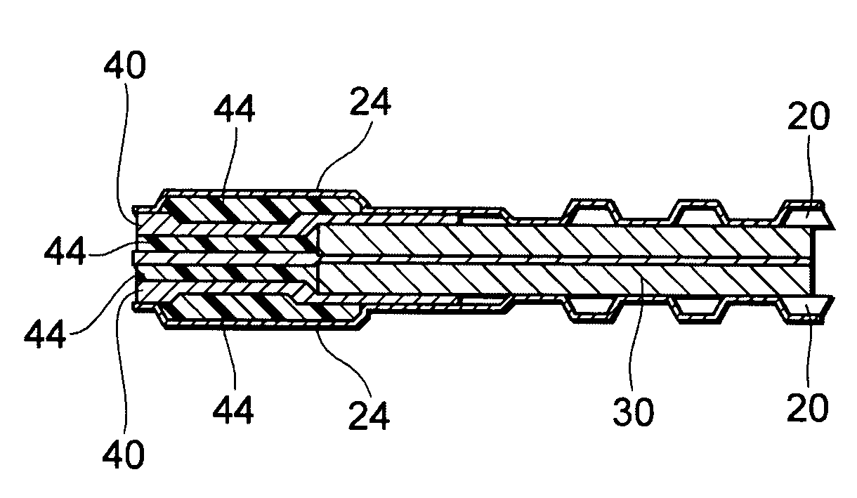
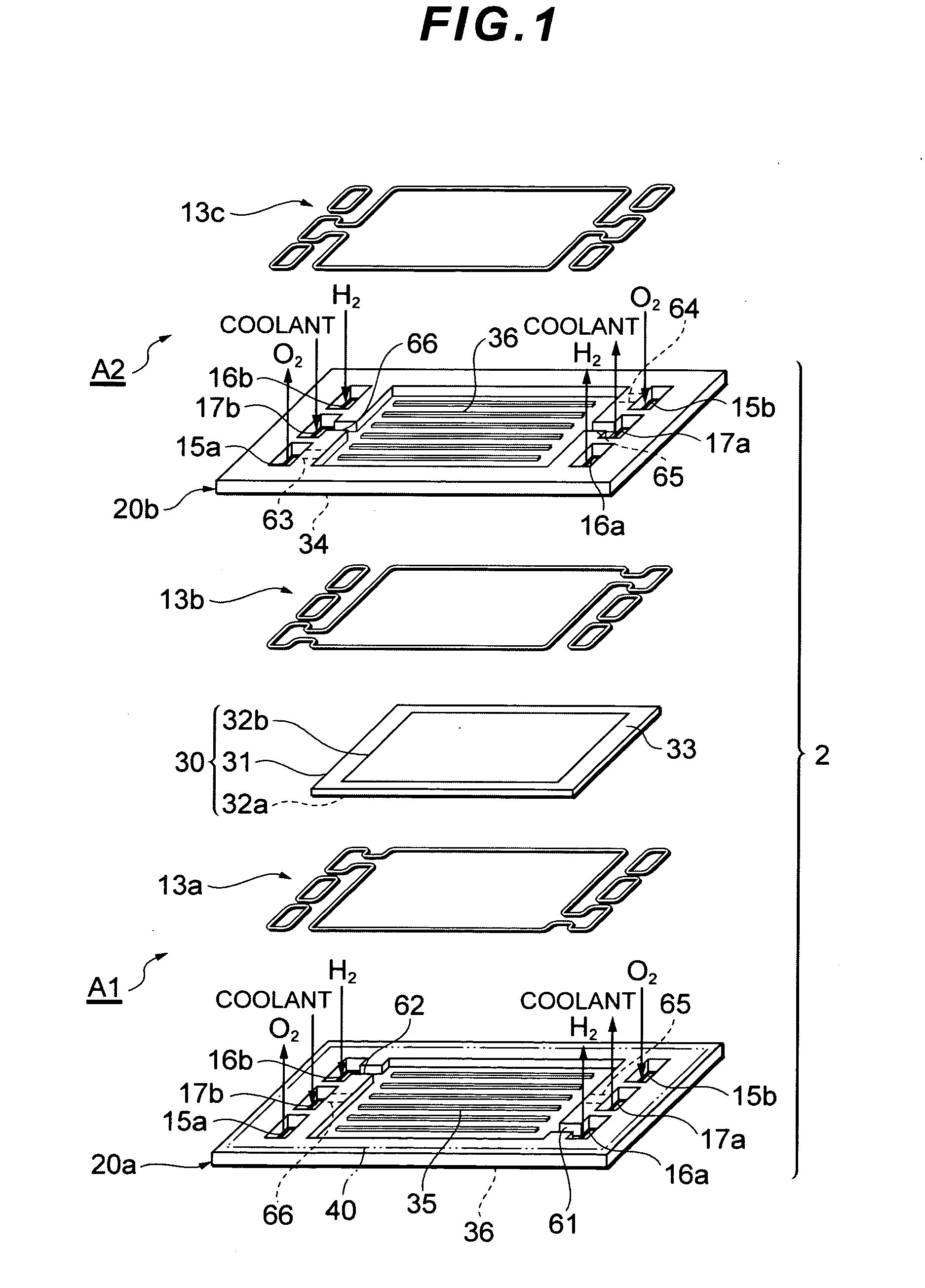
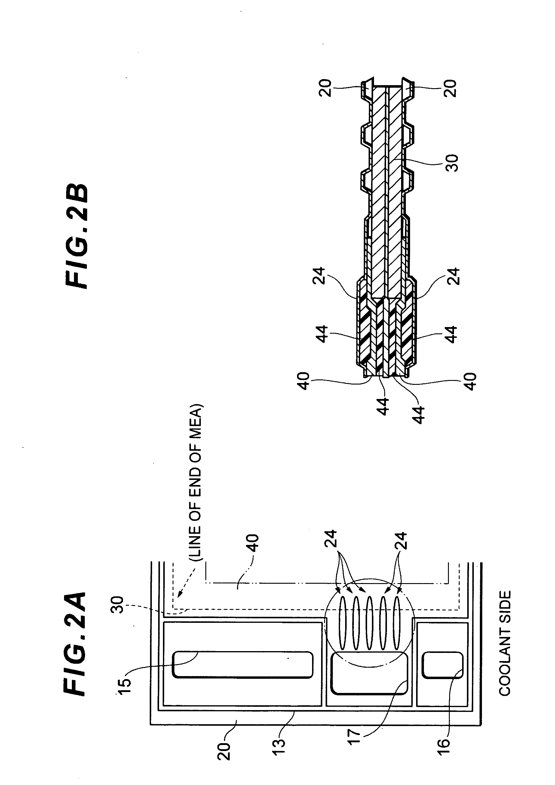
[0031]FIGS. 1 to 7 show a cell laminate 3 and a fuel cell 1 having the same according to the present invention. The cell laminate 3 in each of the embodiments is made by laminating a plurality of separators 20 or plural pairs of separators 20 between which a membrane-electrode assembly 30 is disposed (in FIG. 1, the two separators constituting the cell are shown by reference numerals 20a, 20b). In the present embodiment, one of a power generation region and a refrigerant flow region is formed between the adjacent separators 20 of the cell laminate 3, and to inhibit the deformation of the separators 20, a deformation inhibiting region is further formed therebetween.

[0032]In the embodiment which will hereinafter be described, the schematic constitution of a cell 2 constituting the fuel cell 1 will first be described, and then constitutions of the deformation inhibiting reg...


PUM


Abstract

There is realized a structure particularly suitable for inhibiting deformation of separators having a structure where the shapes of projections and recesses are inverted from each other on the front side and the back side of each separator as in a pressed metal separator. Between adjacent separators, there is formed either a power generation region where MEAs and frame members for holding at least a part of the MEAs are inserted or a refrigerant flow region where neither the MEAs nor the frame members are inserted. A deformation inhibiting region for inhibiting deformation of each separator is formed by a projection provided on the separator. Also, a projection for inhibiting the separator from deforming at the deformation inhibiting region or nearby is formed on each frame member. The projection is projected toward the back side of the deformation inhibiting region, where the deformation inhibiting region is a recess on the back side of the separator.

Description

BACKGROUND OF THE INVENTION[0001]1. Field of the Invention[0002]The present invention relates to a cell laminate and a fuel cell provided with this laminate. More particularly, the present invention relates to the improvement of a structure such as a separator constituting a cell laminate.[0003]2. Description of Related Art[0004]In general, a fuel cell (e.g., a polymer electrolyte fuel cell) is constituted by laminating a plurality of cells each including an electrolyte held between separators. Moreover, the separators are provided with manifolds for supplying or discharging, to or from the cells, a reactant gas (a fuel gas, an oxidizing gas) or a refrigerant for cooling.[0005]Heretofore, as such a separator, a carbon separator or a metal separator has often been used. In a case where the shapes of projections and recesses are formed independently of each other on the front side and backside of, for example, the carbon separator, ribs for backup are sometimes provided on portions wh...

Claims


Application Information

Patent Timeline
IPC IPC(8): H01M2/02
CPCH01M8/0247H01M8/0256H01M8/0258Y02E60/50H01M8/242H01M2008/1095H01M8/0273H01M8/026H01M8/0267H01M8/2483
Inventor HAYASHI, TOMOKAZUYAMAMOTO, YOSHINORIYAGAMI, YUICHIAIZAKI, JIROSHIRAHAMA, JUNICHI
Owner TOYOTA JIDOSHA KK
Why Eureka
Try Eureka