Speech synthesis system and speech synthesis method

a speech synthesis and speech technology, applied in the field of speech synthesis system and speech synthesis method, can solve the problems of high access speed, low access, and difficulty in cost (or price) to store a large amount of speech unit data in an expensive storage medium (e.g., a memory device) with high access speed, and achieve the effect of reducing the cost of speech synthesis

Inactive Publication Date: 2009-01-15
KK TOSHIBA
View PDF9 Cites 11 Cited by
  • Summary
  • Abstract
  • Description
  • Claims
  • Application Information

AI Technical Summary

Problems solved by technology

It is, however, difficult in terms of cost (or price) to entirely store a large amount of speech unit data in an expensive storage medium (e.g., a memory device) with high access speed.
In contrast, if a large amount of speech unit data are entirely stored in a storage medium (e.g., a hard disk) with a relative low cost (or price) and low access speed, it takes too much time to acquire data.
This makes it impossible to perform real-time processing.
This makes it impossible to properly control the worst value of the generation time per unit of processing.
In such an application, if the generation time of synthetic speech in a given unit of processing exceeds the time taken to play back synthetic speech for a preceding unit of processing, sound interruption occurs between units of processing.
This may greatly degrade sound quality.
This may result in failure to achieve optimal sound quality.
If, however, there are many speech units, it still requires much calculation time.
The following problem arises when this method is applied to a beam search under the above restriction.
This problem arises especially when most of speech units are stored in a storage medium with a low access speed and the proportion of speech units stored in a storage medium with a high access speed is very low.
As a consequence, sound quality unevenness occurs in generated synthetic speech, resulting in a deterioration in sound quality as a whole.

Method used


Image

  • Speech synthesis system and speech synthesis method
  • Speech synthesis system and speech synthesis method
  • Speech synthesis system and speech synthesis method

Examples


Embodiment Construction

[0030]An embodiment of the present invention will be described in detail below with reference to the views of the accompanying drawing.

[0031]A text-to-speech system according to an embodiment will be described first.

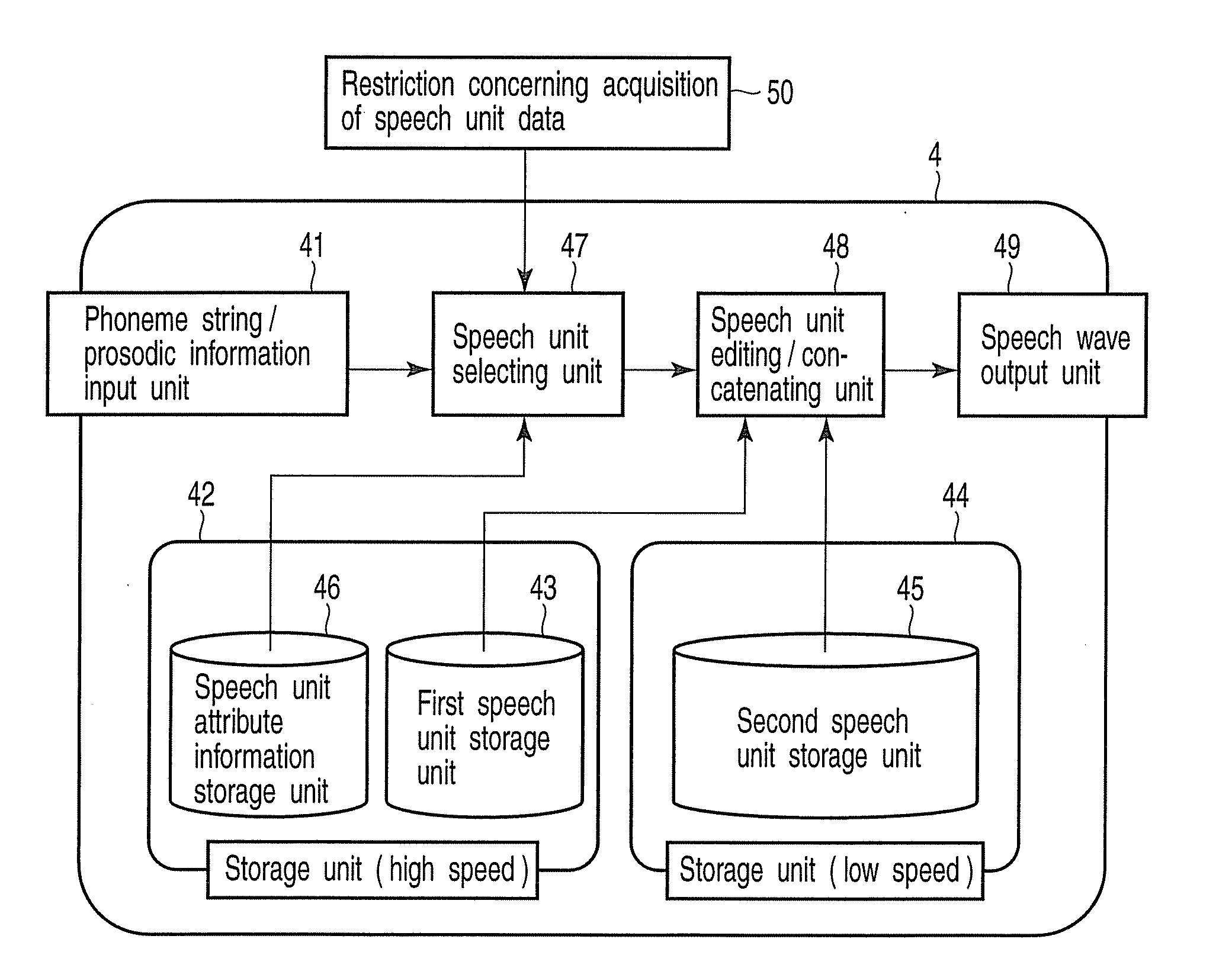
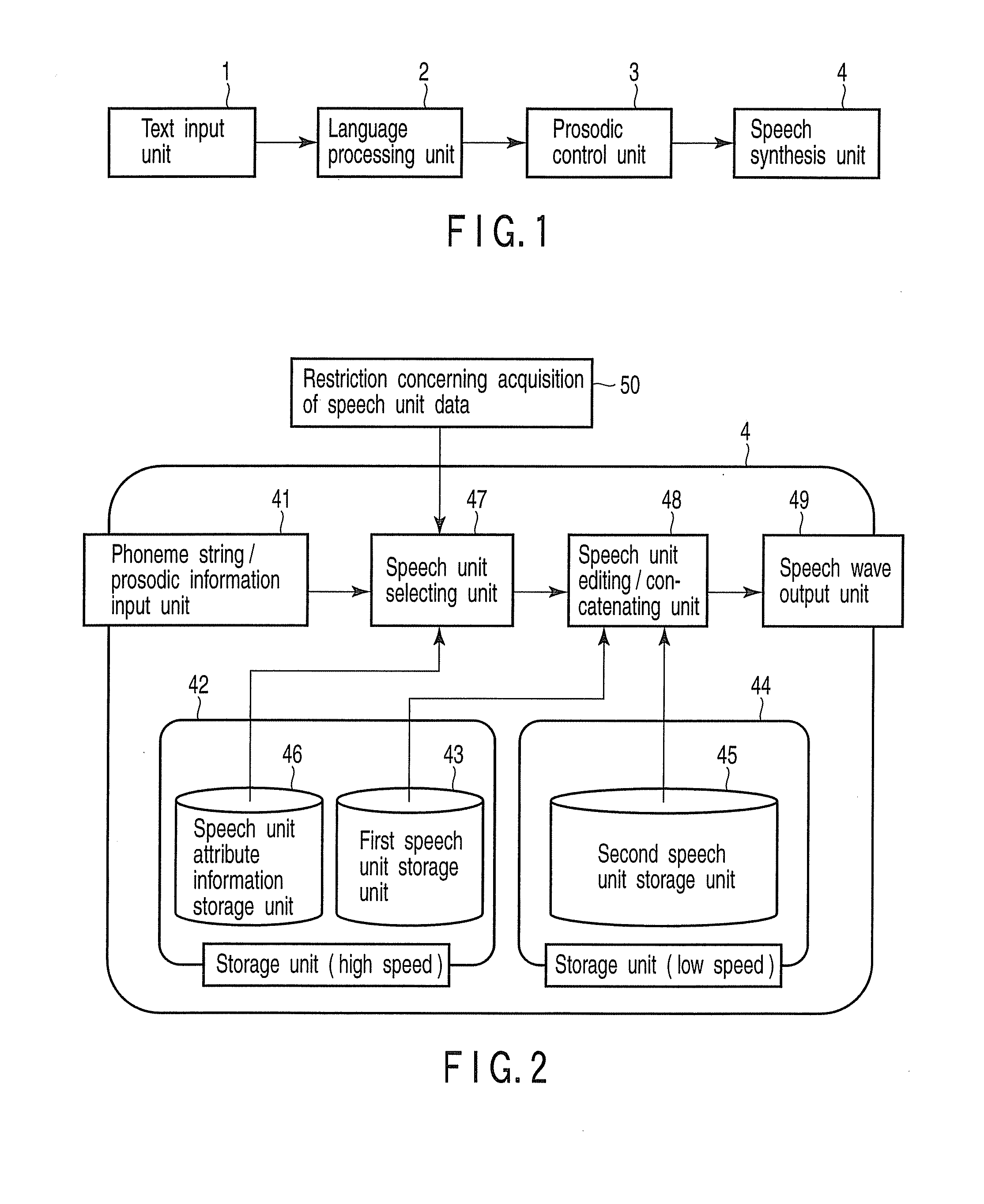
[0032]FIG. 1 is a block diagram showing an arrangement example of the text-to-speech system according to the embodiment. The text-to-speech system comprises a text input unit 1, language processing unit 2, prosodic control unit 3, and speech synthesis unit 4. The language processing unit 2 performs morphological analysis / syntax analysis on the text input from the text input unit 1, and outputs the language analysis result obtained by these language analyses to the prosodic control unit 3. Upon receiving the language analysis result, the prosodic control unit 3 performs accent and intonation processes on the basis of the language analysis result to generate a phoneme string (phoneme symbol string) / prosodic information from the language analysis result, and outputs the gen...


PUM


Abstract

In a speech synthesis, a selecting unit selects one string from first speech unit strings corresponding to a first segment sequence obtained by dividing a phoneme string corresponding to target speech into segments. The selecting unit performs repeatedly generating, based on maximum W second speech unit strings corresponding to a second segment sequence as a partial sequence of the first sequence, third speech unit strings corresponding to a third segment sequence obtained by adding a segment to the second sequence, and selecting maximum W strings from the third strings based on a evaluation value of each of the third strings. The value is obtained by correcting a total cost of each of the third string candidate with a penalty coefficient for each of the third strings. The coefficient is based on a restriction concerning quickness of speech unit data acquisition, and depends on extent in which the restriction is approached.

Description

CROSS-REFERENCE TO RELATED APPLICATIONS[0001]This application is based upon and claims the benefit of priority from prior Japanese Patent Application No. 2007-087857, filed Mar. 29, 2007, the entire contents of which are incorporated herein by reference.BACKGROUND OF THE INVENTION[0002]1. Field of the Invention[0003]The present invention relates to a speech synthesis system and speech synthesis method which synthesize speech from a text.[0004]2. Description of the Related Art[0005]Text-to-speech synthesis is to artificially generate a speech signal from an arbitrary text. The text-to-speech synthesis is generally implemented by three stages, i.e., a language processing unit, a prosodic processing unit, and a speech synthesis unit.[0006]First of all, the language processing unit performs morphological analysis and syntax analysis, and the like on an input text. The prosodic processing unit then performs accent and intonation processes and outputs phoneme string / prosodic information (...

Claims


Application Information

Patent Timeline
Patent Type & Authority Applications(United States)
IPC IPC(8): G10L13/08G10L13/00G10L13/06G10L13/07
CPCG10L13/07
Inventor MORITA, MASAHIROKAGOSHIMA, TAKEHIKO
Owner KK TOSHIBA
Why Eureka
Try Eureka