Sampling filter and radio communication apparatus
- Summary
- Abstract
- Description
- Claims
- Application Information
AI Technical Summary
Benefits of technology
Problems solved by technology
Method used
Image

Examples
embodiment 1
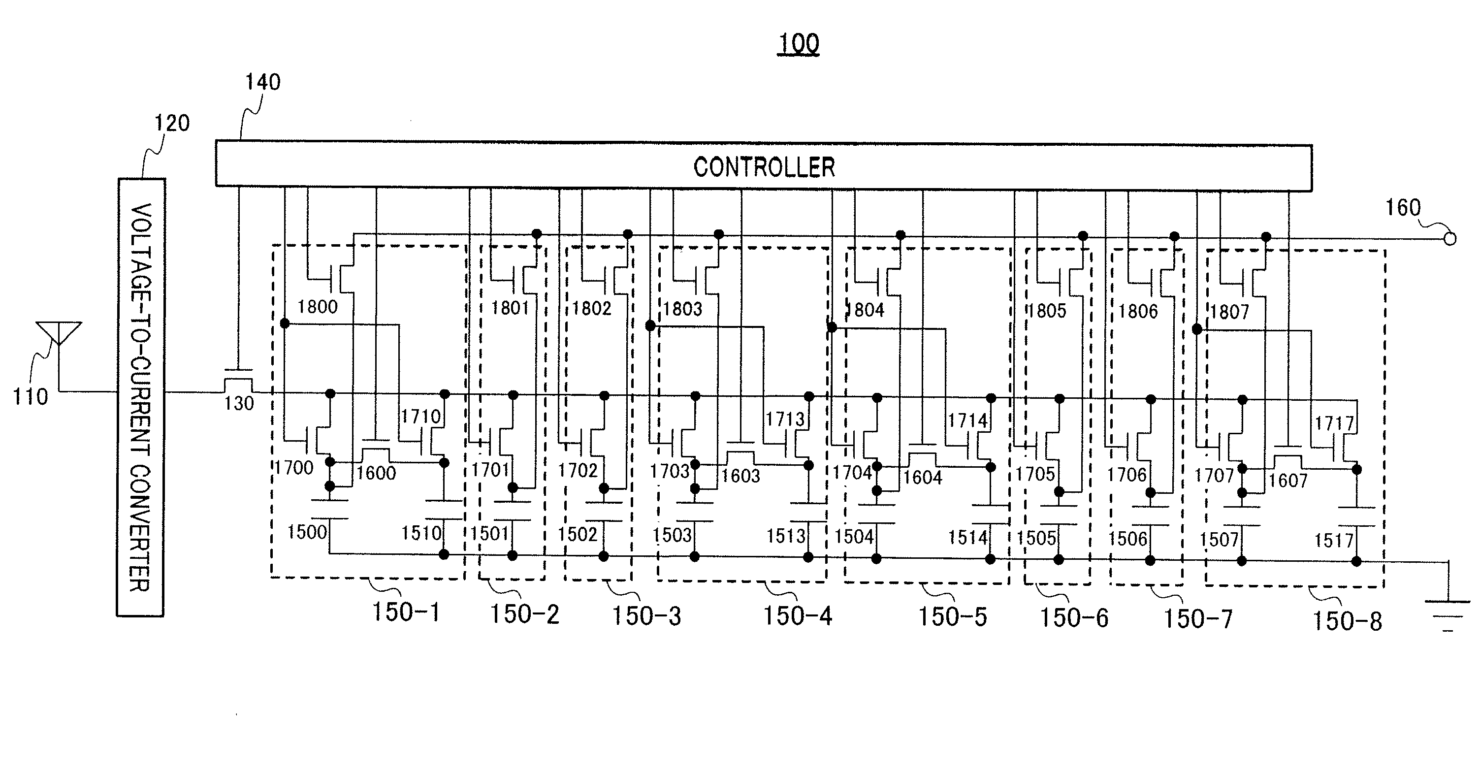
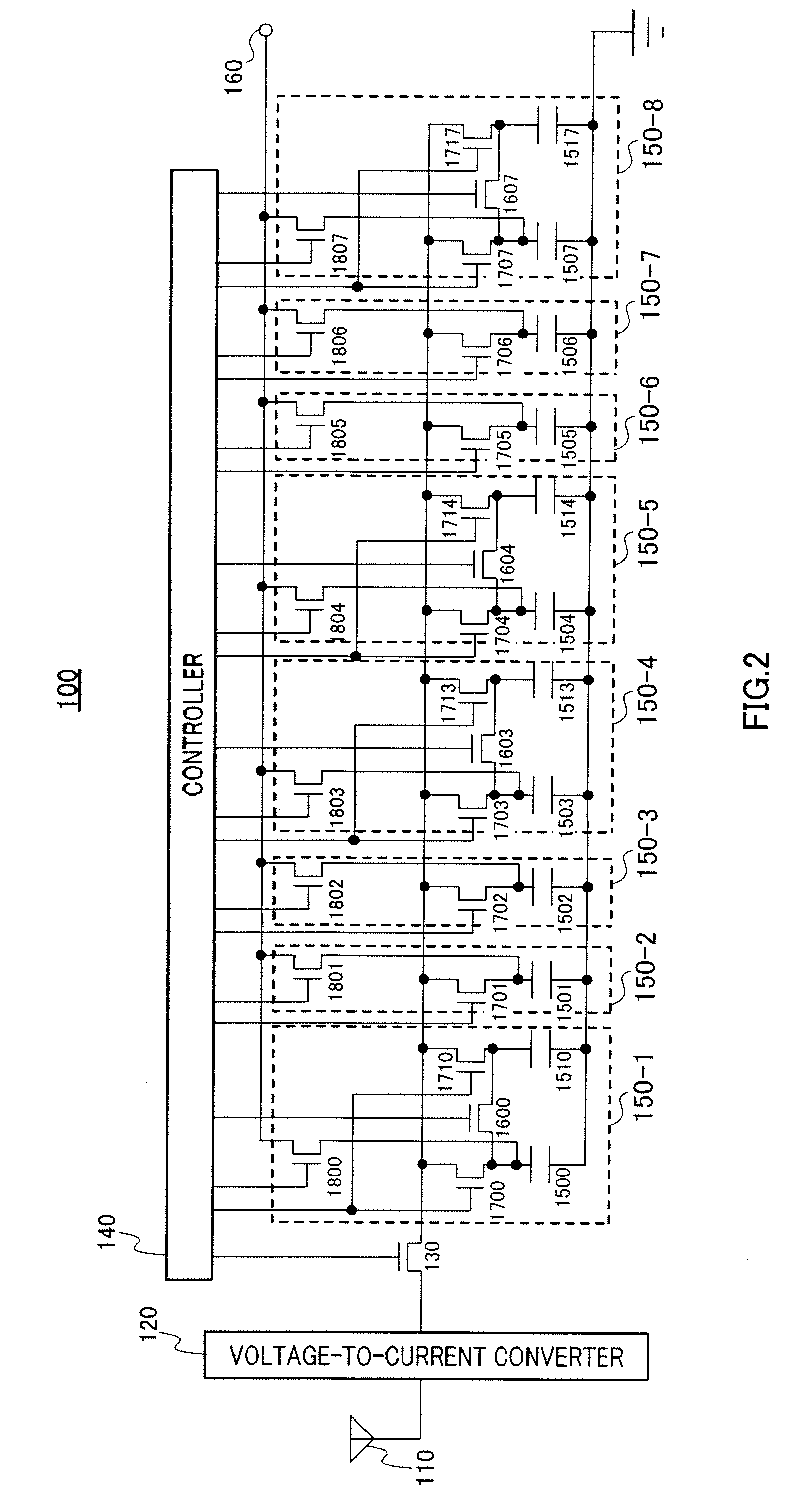
[0033]FIG. 2 shows the configuration of a sampling filter apparatus according to this embodiment. In FIG. 2, the configuration of a sampling filter apparatus having a 4-tap FIR filter characteristic is shown.
[0034]Sampling filter apparatus 100 has antenna 110, voltage-to-current converter 120, sampling switch 130, controller 140, and integration units 150-1 through 150-8. The number of integration units 150 included in sampling filter apparatus 100 is twice the number of taps. Integration units 150-1 through 150-4 form one set, and integration units 150-5 through 150-8 form another set. That is to say, sampling filter apparatus 100 has two sets of integration units, the number of integration units in each set being the same as the number of taps. Integration units 150-1 through 150-8 execute discrete time analog processing. In FIG. 2, terminal 160 connected to circuitry subsequent to sampling filter apparatus 100 is also shown.
[0035]Antenna 110 receives a radio frequency signal tran...
example 1
[0071]Integration unit 150-1 shown in FIG. 5 is formed on a substrate and circuit. Capacitor 1500 has an MEMS structure suspended in space to enable an electrode to be moved by means of an external force such as electrostatic force. Capacitor 1500 has two electrodes facing each other. At least one of these two electrodes, electrode 2000, is movable via an MEMS structure, while electrode 2002 is fixed. In this description, capacitor 1510 is assumed not to have an MEMS structure, and therefore electrodes 2001 and 2003 are fixed.
[0072]The capacitance of a capacitor can generally be expressed as C=e(S / d), where e is permittivity between the electrodes, S is the facing area of the electrodes, and d is the distance between the electrodes.
[0073]That is to say, as can be seen from the above equation, capacitance C can be changed by making facing area S and distance between electrodes d variable by displacing electrodes 2000 and 2001. A capacitor of this embodiment is an MEMS variable-capaci...
example 2
[0078]FIG. 6 shows an integration unit in a case in which the facing area of electrodes is changed by means of an MEMS structure. In integration unit 150-1, one electrode 2000 of capacitor 1500 is displaced, decreasing the facing area of the two electrodes from S to S′. The capacitance of capacitor 1500 then decreases from Q to Q′. A charge can be transferred between the two capacitors by disrupting the balance of the capacity values of capacitor 1500 and capacitor 1510 in this way.
PUM
 Abstract
Description
Claims
Application Information
 - Generate Ideas
- Intellectual Property
- Life Sciences
- Materials
- Tech Scout
- Unparalleled Data Quality
- Higher Quality Content
- 60% Fewer Hallucinations
Browse by: Latest US Patents, China's latest patents, Technical Efficacy Thesaurus, Application Domain, Technology Topic, Popular Technical Reports.
© 2025 PatSnap. All rights reserved.Legal|Privacy policy|Modern Slavery Act Transparency Statement|Sitemap|About US| Contact US: help@patsnap.com