Apparatus and Method for Detecting Output Power From an Amplifier

a technology of output power and amplifier, applied in amplifiers, gain control, frequency analysis, etc., can solve the problems of power sensor occupying additional space, reducing the power of signal to the antenna b, and adding insertion loss between the amplifier and the antenna

Inactive Publication Date: 2009-01-22
DRAGONWAVE
View PDF7 Cites 22 Cited by
  • Summary
  • Abstract
  • Description
  • Claims
  • Application Information

AI Technical Summary

Benefits of technology

[0007]In some embodiments, the predetermined level is selected to provide a DC bias current / voltage different from that at a lower output power level. For example, the predetermined level may be sufficient to at least partially saturate the amplifier. As the amplifier is driven towards saturation, the DC bias current may exhibit a non-linear dependency on output power level, and the DC bias current can change significantly in this region, facilitating the detection of output power from the amplifier.
[0044]In some embodiments, the signal applied to the amplifier comprises a modulated tone. Advantageously, modulation may be applied to the signal tone (e.g. carrier wave tone) in order to control (e.g. increase) the power of the output signal from the amplifier, to assist in detection of output power from the amplifier.

Problems solved by technology

A drawback of this current arrangement is that the power sensor, which typically comprises an RF coupler, a Schottky diode and a DC amplifier, draws power from the output of the power amplifier, thereby reducing the power of the signal to the antenna 15.
This is predominantly caused by the rf coupler which adds insertion loss between the amplifier and antenna.
A further drawback of this arrangement is that the power sensor takes up additional space between the output of the amplifier and the antenna and adds cost to the transmitter.

Method used


Image

  • Apparatus and Method for Detecting Output Power From an Amplifier
  • Apparatus and Method for Detecting Output Power From an Amplifier
  • Apparatus and Method for Detecting Output Power From an Amplifier

Examples


Embodiment Construction

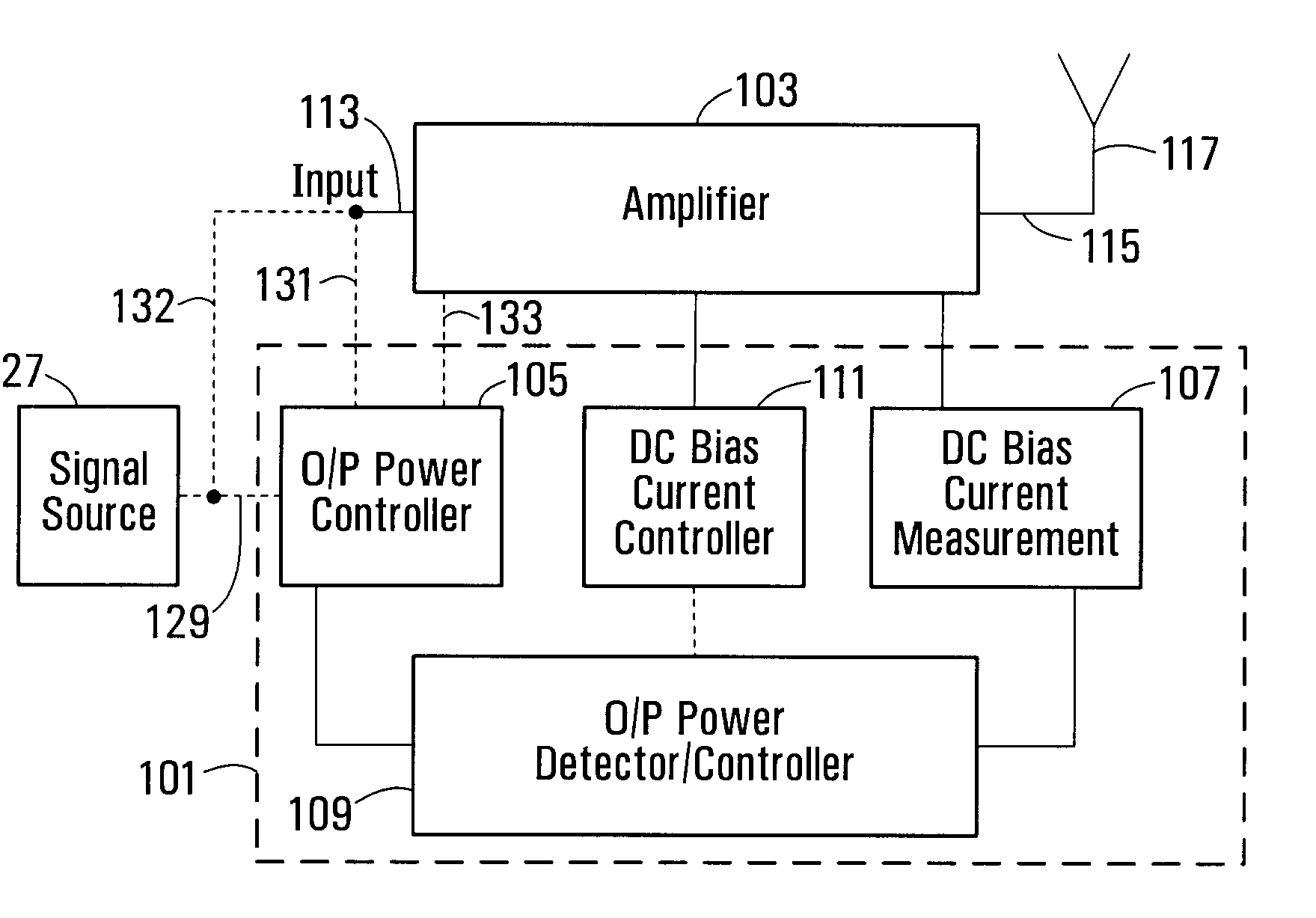
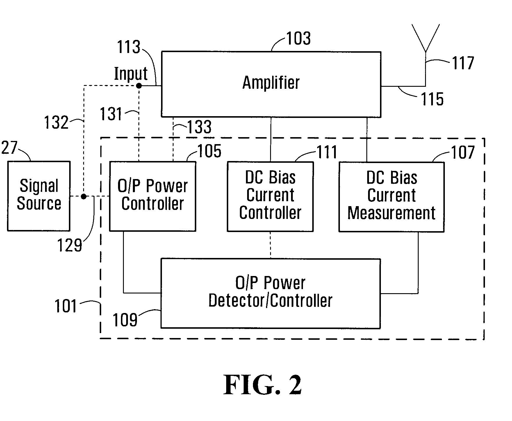
[0060]Referring to FIG. 2, an apparatus 101 for detecting output power from an amplifier 103 comprises an output power controller 105 for controlling the output power from the amplifier, a DC bias current measuring device 107 for measuring DC bias current / voltage at an output 115 from the amplifier 103 and an output power detector / controller 109 for detecting output power from the amplifier. The output power detector 109 is configured to control the output power controller 105 to implement the detection method, as described in more detail below, and to determine whether or not there is output power from the amplifier based on DC bias current measurement(s) made by the bias current measurement device 107.

[0061]A dc voltage source is typically provided to bias the amplifier, the voltage source providing either a fixed voltage or variable voltage.

[0062]The apparatus 101 may optionally include a DC bias current controller 111, which may be controllable by an operator and / or by the outpu...


PUM


Abstract

An apparatus for detecting output power from an amplifier (103) comprises a first controller (105) for controlling output power of a signal from the amplifier (103), a device (107) for measuring dc bias current / voltage at an output (115) of the amplifier (103), second controller (109) operative to set the first controller (105) to a setting corresponding to an output power at a finite level, and a detector (109) for determining whether or not there is output power from the amplifier based on the measured dc bias current / voltage at the setting of the first controller (105). In one embodiment, the first controller (105) is set at a setting corresponding to an output power level which is sufficient to at least partially saturate the amplifier (103).

Description

FIELD OF THE INVENTION[0001]The present invention relates to apparatus and methods for detecting output power from an amplifier, and in particular, but not limited to detecting output power from a power amplifier of a radio transmitter.BACKGROUND OF THE INVENTION[0002]A typical radio transmitter for use in wireless communication networks is shown in FIG. 1. The transmitter 1 comprises an upconverter 3 which includes a mixer 5 having a signal input 7 and a local oscillator 9, a filter 11, a power amplifier 13 and an antenna 15. The transmitter further comprises a DC bias current controller 17, a DC bias current measurement device 19 and a power sensor 21 coupled to the output 23 of the amplifier for measuring the output power of the amplifier 13. The upconverter may have a number of mixers so that upconversion is performed in multiple stages, and an additional filter(s) may be included between one mixer stage and another. A filter may also be inserted between the power amplifier 13 a...

Claims


Application Information

Patent Timeline
Patent Type & Authority Applications(United States)
IPC IPC(8): G01R21/06
CPCG01R31/2822G01R31/3161H03F1/0205H03F1/0261H03G3/3042H03F1/301H03F2200/393H03F2200/447H03F2200/465H03F1/30
Inventor ROMANO, ANTONIO
Owner DRAGONWAVE
Why Eureka
Try Eureka