
Device and method for estimating the number of arrival signals

a technology of arrival signal and device, applied in direction finders using radio waves, multi-channel direction-finding systems using radio waves, instruments, etc., can solve the problem of large number of snapshots that cannot be secured in a short period of time, and achieve the effect of enhancing the reliability of detection results

Inactive Publication Date: 2009-01-22
DENSO CORP
View PDF16 Cites 22 Cited by
  • Summary
  • Abstract
  • Description
  • Claims
  • Application Information

AI Technical Summary

Benefits of technology

[0018]The present invention has been achieved to solve the above-described issues. An object of the present invention is to provide a method for estimating the number of arrival signals with high accuracy, even when a number of snapshots is small, and a radar device using the number of arrival signals estimating method.
[0020]In the method for estimating number of arrival signals of the present invention, identification is made using the ratio to the reference eigenvalue, namely relative size. Therefore, the eigenvalues can be accurately identified and the number of arrival signals L can be accurately estimated even when a number of snapshots is small or when overall reception strength is boosted.
[0024]In other words, the radar device of the present invention uses the method for estimating number of arrival signals and can achieve the same effects as the method. Moreover, the radar device can enhance estimation accuracy of the direction of arrival of the incident radar waves.
[0027]In this case, the frequency at which the frequency spectrum of the beat signal peaks suggests existing one distinct object having a distance and a relative speed specified by the frequency. Therefore, using this frequency can prevent the number of arrival signals from being determined regardless of the reference eigenvalue being in the noise space (in other words, regardless of the number of arrival signals is zero). In other words, the reference eigenvalue is definitely an eigenvalue of the signal space. As a result, reliability of detection results can be enhanced.

Problems solved by technology

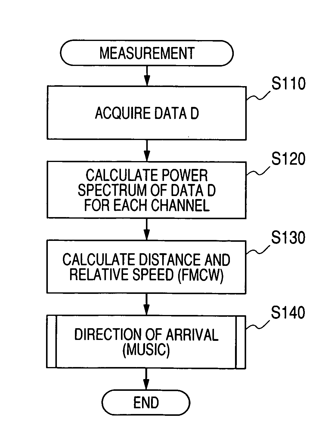
In particular, as with a frequency modulated continuous wave (FMCW) radar, when only a single snapshot (only a frequency that peaks in a frequency spectrum of a beat signal) can be obtained at a time for a single object at a single instance of measurement, a large number of snapshots cannot be secured during a short period of time.

Method used


Image

  • Device and method for estimating the number of arrival signals
  • Device and method for estimating the number of arrival signals
  • Device and method for estimating the number of arrival signals

Examples


Embodiment Construction

[0034]Embodiments of the present invention will be described with reference to the drawings.

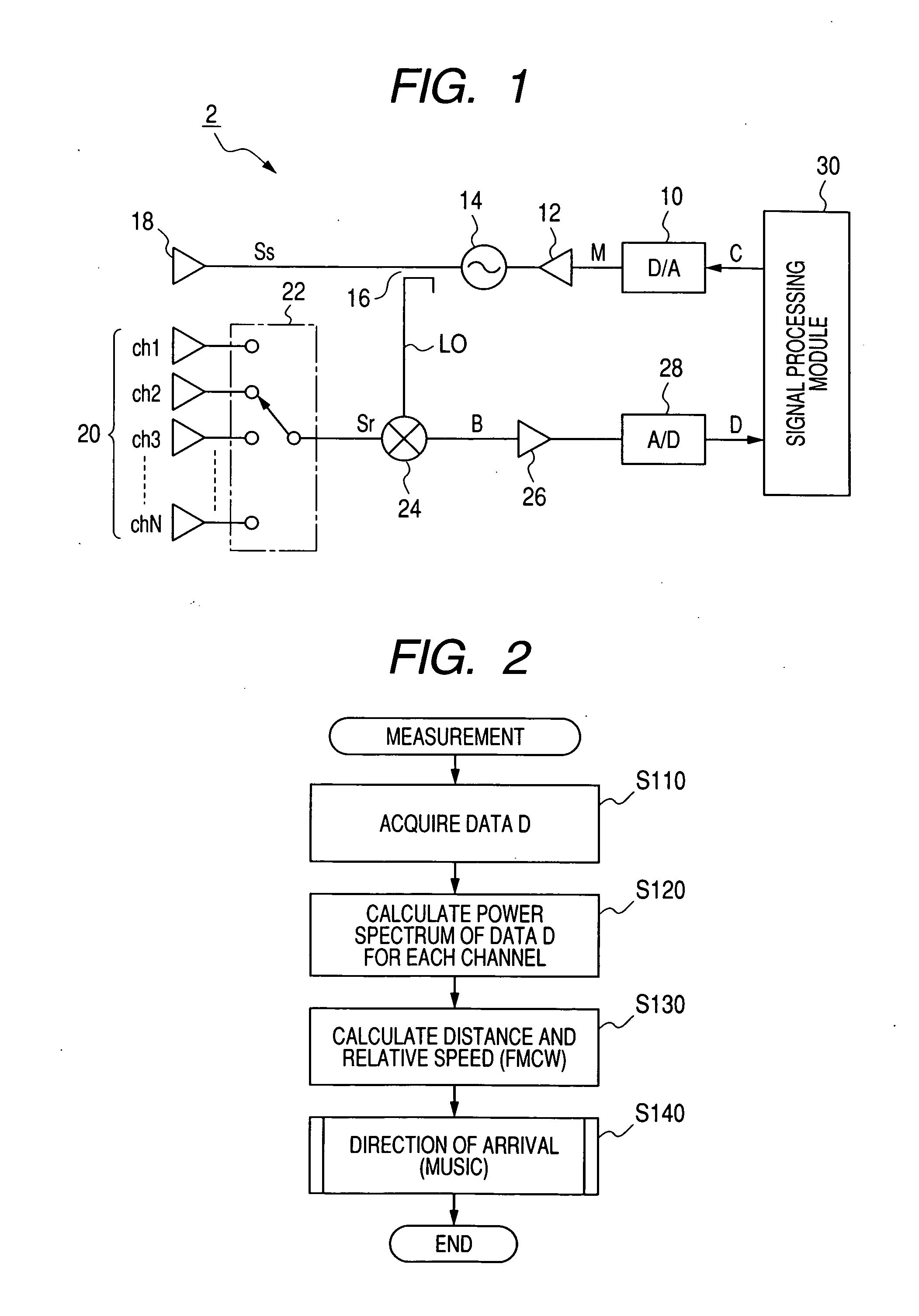
[0035]FIG. 1 is a block diagram of an overall configuration of a radar device 2 to which the present invention is applied.

[0036]The radar device 2 is mounted on a vehicle. The radar device 2 is configured as a portion of an object recognition device for a vehicle that recognizes an object present in front of the vehicle.

[0037]As shown in FIG. 1, the radar device 2 includes a digital-to-analog (D / A) converter 10, a voltage controlled oscillator (VCO) 14, a distributor 16, and a transmission antenna 18. The D / A converter 10 generates a triangular wave modulation signal M in adherence to a modulation instruction C. The modulation signal M generated by the D / A converter 10 is applied to the VCO 14, via the buffer 12. The VCO 14 changes oscillation frequency in adherence to the modulation signal M. The distributor 16 performs power distribution, dividing an output from the VCO 14 into a transmissi...


PUM


Abstract

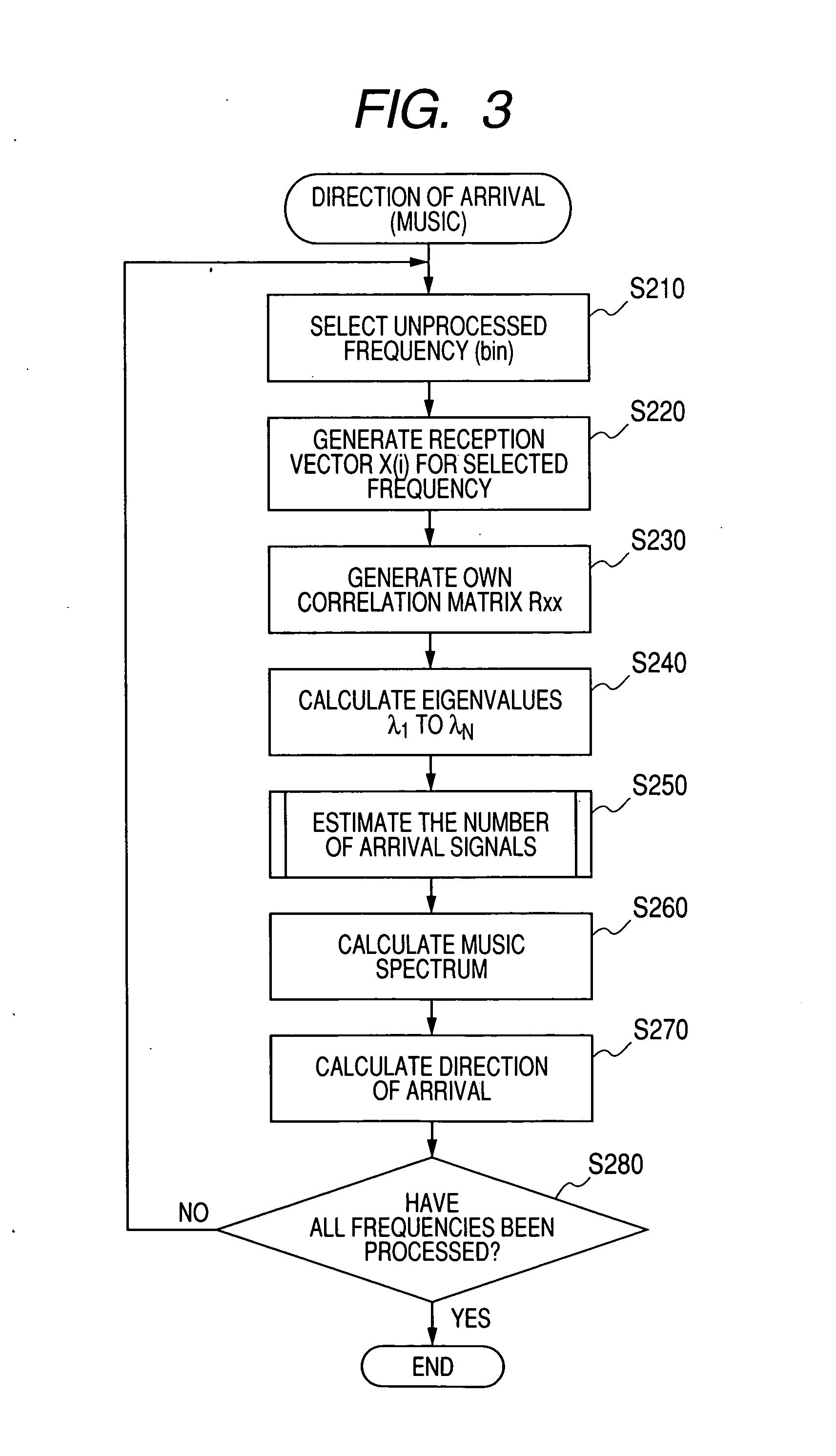
A largest eigenvalue is determined among eigenvalues corresponding to a correlation matrix indicating correlations between a plurality of channels receiving incoming radar waves from an object that reflects a radar wave as a reference eigenvalue λ1. A ratio Rλi (=10 log 10(λi / λ1)) is calculated of each eigenvalue λ2 to λN to the reference eigenvalue λ1. Eigenvalues among the reference eigenvalue λ1 and the eigenvalues λ2 to λN of which the eigenvalue ratio Rλi is greater than a noise threshold TH are identified as eigenvalues in signal space. Eigenvalues of which the eigenvalue ratio Rλi is equal to the noise threshold TH or less are identified as eigenvalues in noise space. The number of eigenvalues identified as the eigenvalues in signal space is counted as the number of arrival signals.

Description

CROSS-REFERENCE TO RELATED APPLICATION[0001]This application is related to Japanese Patent Application NO. 2007-189683 filed on Jul. 20, 2007, the contents of which are hereby incorporated by reference.BACKGROUND OF THE INVENTION[0002]1. Field of the Invention[0003]The present invention relates to a radar device, and in particular to a radar device receiving incident waves including reflected radar waves from an object using a plurality of channels and, based on a correlation matrix indicating correlations of reception signals between reception channels, estimating the number of arrival signals (i.e., estimates the number of distinct reflection waves).[0004]2. Description of the Related Art[0005]Conventionally, a following radar device is known. The radar device uses an array antenna configured by a plurality of antenna elements and estimates a direction of arrival (DOA) of a plurality of radio waves simultaneously arriving at the array antenna.[0006]As a method of estimating the DO...

Claims


Application Information

Patent Timeline
Patent Type & Authority Applications(United States)
IPC IPC(8): G01S7/295G01S13/02G06F17/40
CPCG01S3/74G01S2013/0263G01S13/34G01S13/06
Inventor ABE, YOSHIHIROSHIMIZU, KOUJI
Owner DENSO CORP
Learn More