Fluid ejecting apparatus and fluid filling method of fluid ejecting apparatus

Active Publication Date: 2009-01-22
SEIKO EPSON CORP
View PDF7 Cites 5 Cited by
  • Summary
  • Abstract
  • Description
  • Claims
  • Application Information

AI Technical Summary

Benefits of technology

[0010]An advantage of some aspects of the invention is that makes it possible to suppress entry of foreign matter into a fluid containing portion in a fluid ejecting apparatus before the apparatus is used.

Problems solved by technology

In addition, when the printer is manufactured without an attached ink container, the quality of ink in the recording head may possibly deteriorate because air may be allowed to enter the ink flow passage or the ink container.
These problems not only apply to ink jet printers including ink containers that contain liquid ink and recording head that discharges liquid ink, but also apply to all fluid ejecting apparatuses that include a fluid containing portion that contains fluid and a fluid discharge portion that discharges fluid.

Method used


Image

  • Fluid ejecting apparatus and fluid filling method of fluid ejecting apparatus
  • Fluid ejecting apparatus and fluid filling method of fluid ejecting apparatus
  • Fluid ejecting apparatus and fluid filling method of fluid ejecting apparatus

Examples


first embodiment

A. First Embodiment

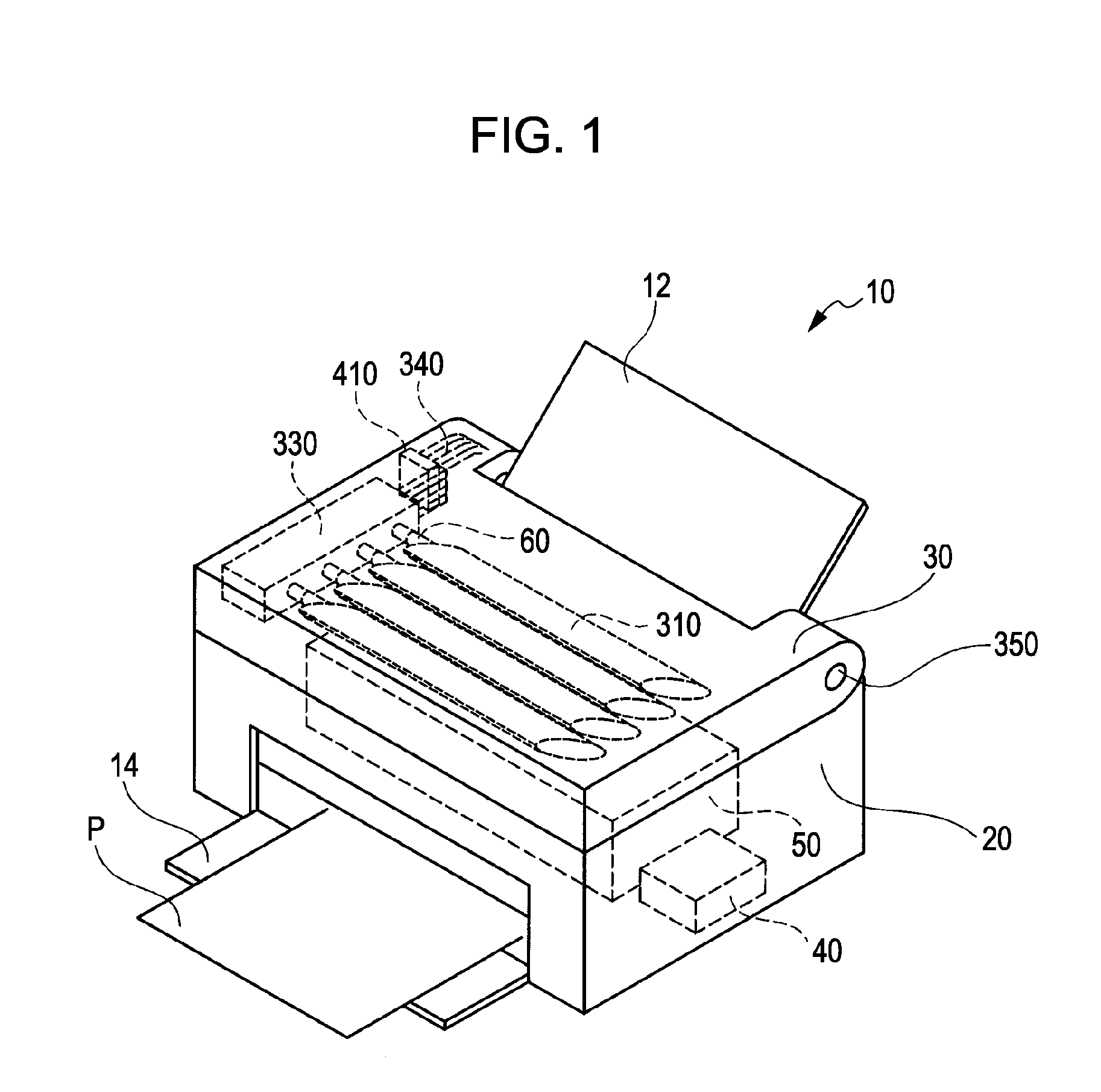
[0045]FIG. 1 is a perspective view that illustrates the configuration of a printer 10, which serves as an example of fluid ejecting apparatus capable of being used in association with the present invention. The printer 10 is a first embodiment of the invention. The printer 10 is an ink jet printer that prints characters or figures by ejecting liquid ink, comprising a fluid, onto a print sheet P, which serves as a recording medium.

[0046]The printer 10 includes a main housing 20 that accommodates a print mechanism portion 50. The main housing 20 is provided with a paper feed tray 12 and a paper output tray 14. The paper feed tray 12 introduces a print sheet P, which is supplied to the print mechanism portion 50, into the main housing 20. The paper output tray 14 delivers a print sheet P, which is ejected from the print mechanism portion 50, outward from the main housing 20. The details of the print mechanism portion 50 will be described more fully below.

[0047]A cont...

second embodiment

B. Second Embodiment

[0073]FIG. 11 is a top view that illustrates the internal configuration of the upper housing 30 of the printer 10 according to a second embodiment. The second embodiment differs from the first embodiment shown in FIG. 4 in that the printer 10 of the second embodiment includes a choke valve mechanism 900. The choke valve mechanism 900 is arranged near a position at which the ink supply portion 330 is connected to the supply tube 340. The choke valve mechanism 900, as described more fully below, is configured to open or close the ink flow passage that extends from the ink packs 310 to the recording head 810.

[0074]FIG. 12 illustrates the configuration of the choke valve mechanism 900. FIG. 13A and FIG. 13B are cross-sectional views that are taken along the line XIIIA-XIIIA in FIG. 12. As shown in FIG. 12, the choke valve mechanism 900 includes a choking DC motor 910, a gear train 920 and a magnet portion 930. The gear train 920 transmits the rotary torque of the cho...

third embodiment

C. Third Embodiment

[0092]FIG. 18 is a flowchart that illustrates an ink filling process of the printer 10 according to a third embodiment. The ink filling process of the third embodiment, as well as the ink filling process of the second embodiment (see FIG. 17), is, for example, performed at the last shipping preparation stage of the manufacturing process of the printer 10. However, the flowchart shown in FIG. 18 differs from the flowchart shown in FIG. 17 in that a cleaning process for the ink supply system (steps S60 to S90) is also included.

[0093]As shown in FIG. 18, at step S60, a cleaning jig is attached to the printer 10 and then the ink supply system is cleaned. In step S70, cleaning fluid is supplied to fill the ink supply system. In the present embodiment, a distribution-purpose ink is used as the cleaning fluid. The distribution-purpose ink used in the present embodiment contains water, as a base, humectant, and surfactant but does not contain a color material (dye or pigm...


PUM


Abstract

A fluid ejecting apparatus includes a fluid containing portion, a fluid discharging portion, a flow passage forming portion and a valve mechanism. The fluid containing portion contains fluid. The fluid discharging portion discharges the fluid. The flow passage forming portion forms a fluid flow passage that extends from the fluid containing portion to the fluid discharging portion. The valve mechanism is able to open or close the fluid flow passage. The fluid ejecting apparatus is placed in an initial state before an initial use of the fluid ejecting apparatus, wherein fluid is contained in the fluid containing portion and at least portion of the fluid flow passage from a position of the fluid containing portion to a position of the valve mechanism is filled with the fluid and the fluid flow passage is closed by the valve mechanism.

Description

CROSS REFERENCES TO RELATED APPLICATIONS[0001]The entire disclosure of Japanese Patent Application No. 2007-189068, filed Jul. 20, 2007, Japanese Patent No. 2007-189075, filed Jul. 20, 2007, and Japanese Patent No. 2007-318034, filed Dec. 10, 2007 are expressly incorporated herein by reference.BACKGROUND OF THE INVENTION[0002]1. Technical Field[0003]The present invention relates to a fluid ejecting apparatus. More specifically, the present invention relates to a system and method for supplying fluid within a fluid ejecting apparatus.[0004]2. Related Art[0005]One example of a fluid ejection apparatus currently known in the art is an ink jet printer which includes a recording head which is filled with an ink or a preservative solution during the manufacturing process, such as in the apparatuses described in JP-A-2002-283590 and JP-A-2004-114647, which are referred to as off-carriage printers.[0006]In another configuration currently known in the art, the fluid ejecting apparatus is an ...

Claims


Application Information

Patent Timeline
IPC IPC(8): B41J2/175
CPCB41J29/02B41J2/17509
Inventor SEINO, TAKEOTAKEKOSHI, TAROKOBAYASHI, NORIHISAROKUHARA, NORITSUNA
Owner SEIKO EPSON CORP
Why Eureka
Try Eureka