Exposure method and apparatus

a technology applied in the field of exposure method and apparatus, can solve the problems of not always efficient methods, and achieve the effects of accurate movement of the imaging position of each light beam, easy correction of imaging position, and accurate movement of imaging position

Inactive Publication Date: 2009-01-22
FUJIFILM CORP
View PDF10 Cites 29 Cited by
  • Summary
  • Abstract
  • Description
  • Claims
  • Application Information

AI Technical Summary

Benefits of technology

[0033]In the first exposure method and apparatus of the present invention, the imaging position of each of light beams by the first imaging optical system and/or the second imaging optical system is controlled separately for each of the light beams so that an image of a two-dimensional pattern formed on the photosensitive material coincides with an intended two-dimensional pattern. Therefore, it is possible to more easily correct the imaging position of each of the light beams, for example, without generating a new control signal for controlling the spatial light modulation means or the like. Further, since the imaging positions of the light beams are corrected separately for each of the light beams, it is possible to smooth a variation in an exposure light amount at an edge portion forming the outline of a two-dimensional pattern formed on the photosensitive material, for example. Alternatively, it is possible to form an image of each of the light beams on the photosensitive material by shifting the position of each of the light beams.
[0034]In the second exposure method and apparatus of the present invention, the imaging position of each of light beams by the first imaging optical system is controlled separately for each of the light beams so that an image of a two-dimensional pattern formed on the photosensitive material coincides with an intended two-dimensional pattern. Therefore, it is possible to more easily correct the imaging position of eac

Problems solved by technology

However, the method in which the spatial light modulation is performed in such a manner that the shift in the imaging position of each of the light

Method used


Image

  • Exposure method and apparatus
  • Exposure method and apparatus
  • Exposure method and apparatus

Examples


first embodiment

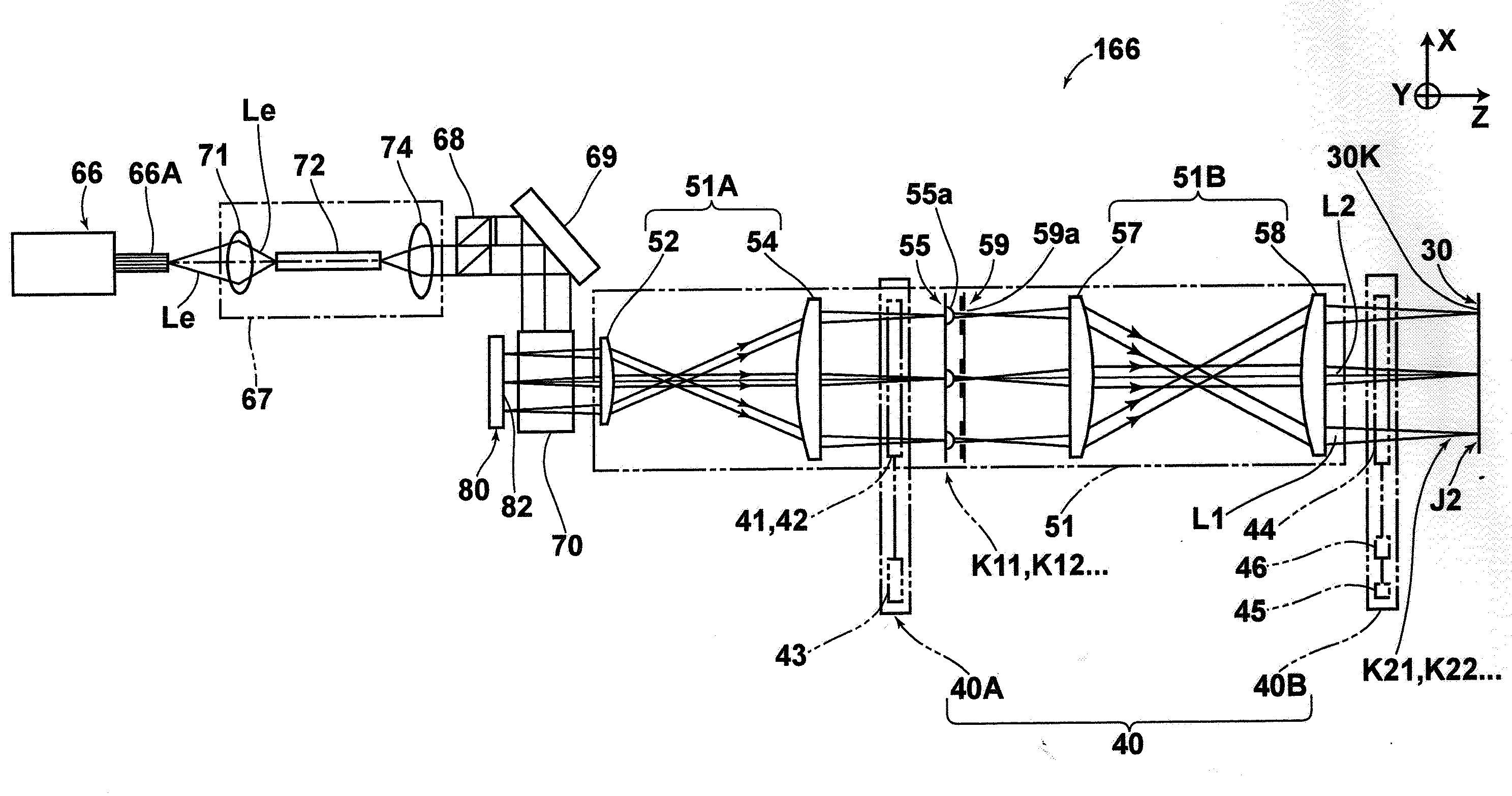
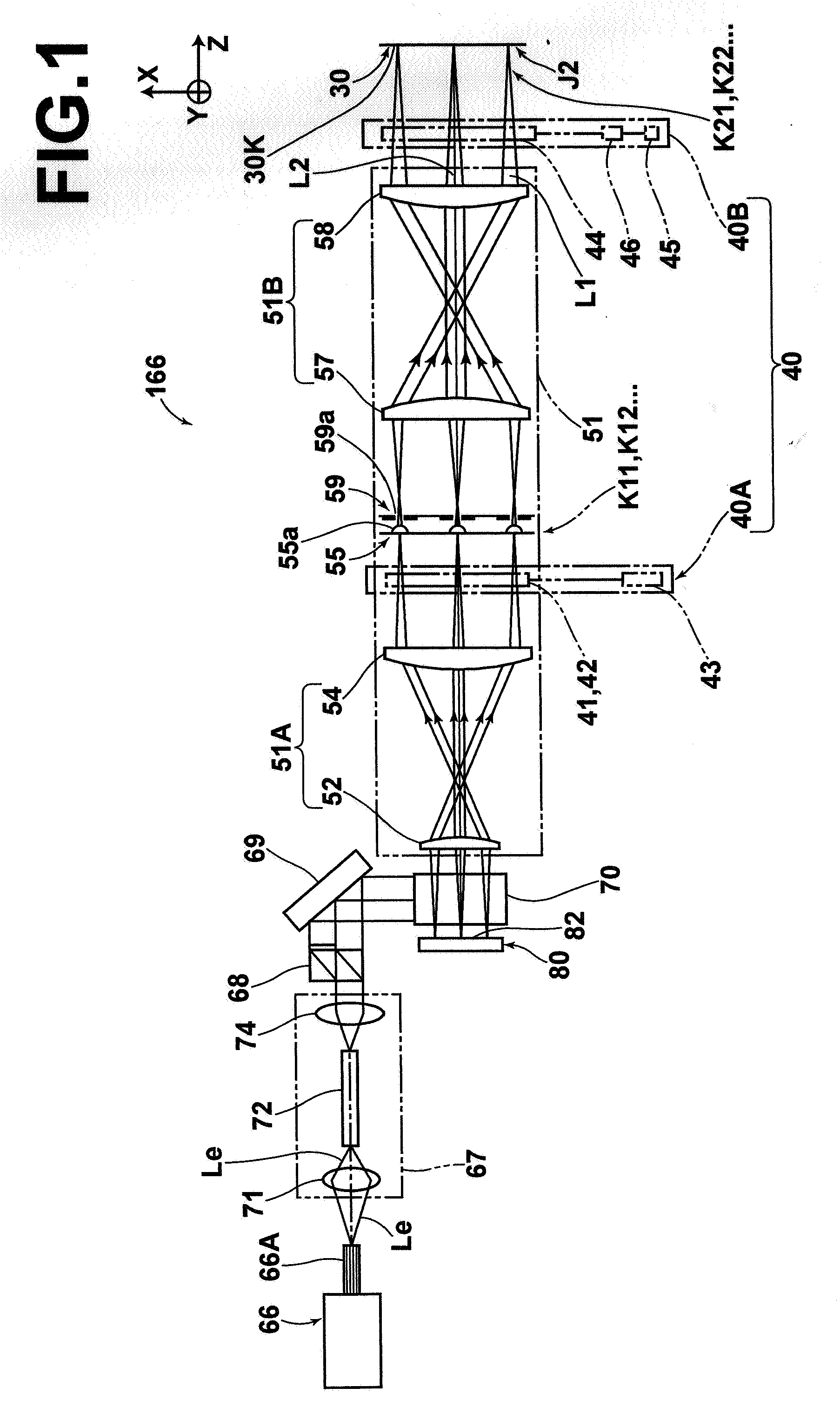
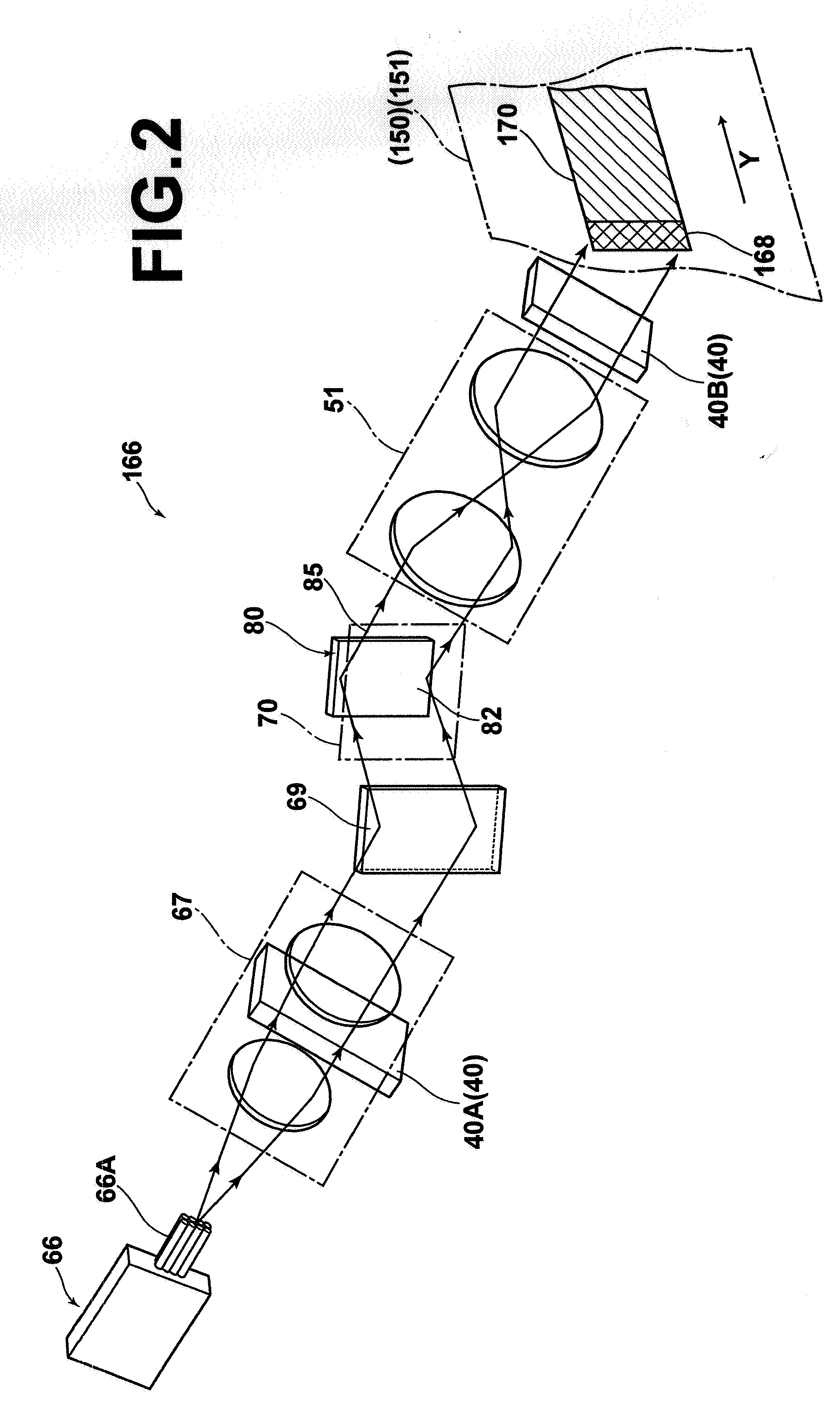
[0058]Hereinafter, the present invention will be described with reference to the drawings. FIG. 1 is a diagram illustrating an optical path of an optical system of an exposure head included in an exposure apparatus. FIG. 2 is a schematic perspective view illustrating the configuration of the optical system. FIG. 3 is a diagram illustrating the process in which a polarization unit causes the polarization direction of laser light emitted from a light source to become uniform. FIG. 4 is a partial enlarged diagram of a multiplicity of two-dimensionally-arranged micromirrors. FIGS. 5A and 5B are diagrams illustrating operations for reflecting light by micromirrors. FIGS. 6A and 6B are diagrams illustrating examples of used areas of micromirrors in a DMD.

[0059]An exposure apparatus that carries out an exposure method of the present invention is used to produce printed circuit boards. The exposure apparatus exposes a material for printed circuit boards, the material being formed by deposit...

second embodiment

[0121]As illustrated in FIG. 15, an imaging position correction unit 40′ in the exposure apparatus includes only a first imaging position correction unit 40A. The first imaging position correction unit 40A is a liquid crystal device for correcting the imaging position of an image of each of light beams formed by the first imaging optical system 51A. The first imaging position correction unit 40A includes the shift-direction correction device 41, the focus-direction correction device 42 and the voltage application unit 43, as already described. The voltage application unit 43 applies a voltage for forming an electric field in each of liquid crystal layers of the shift-direction correction device 41 and the focus-direction correction device 42. Further, an imaging optical system 51′ for forming an image of each of light beams, on which spatial light modulation has been performed by the DMD 80, on the photosensitive material 30K in the material 30 for printed circuit boards includes o...


PUM


Abstract

When an image of a two-dimensional pattern is formed on a photosensitive material by performing spatial light modulation on light emitted from a light source by a spatial light modulation means including a multiplicity of arranged pixel units and by forming an image by a second imaging optical system after forming an image of each of light beams corresponding to the pixel units, on which the spatial light modulation has been performed, by a first imaging optical system, the imaging position of each of light beams is controlled separately for each of the light beams. Accordingly, the image of the two-dimensional pattern formed on the photosensitive material coincides with an intended two-dimensional pattern.

Description

TECHNICAL FIELD[0001]The present invention relates to an exposure method and apparatus. Particularly, the present invention relates to an exposure method and apparatus for exposing a photosensitive material to light by forming an image of a two-dimensional pattern on the photosensitive material. The image of the two-dimensional pattern is formed by performing spatial light modulation on light emitted from a light source by reflecting the light by a multiplicity of pixel units and by forming an image of each of light beams corresponding to the pixel units.BACKGROUND ART[0002]Conventionally, an exposure apparatus for producing printed circuit boards by exposing a photosensitive material deposited on a surface of a substrate to light is well known. In the exposure apparatus, the photosensitive material is exposed to light by forming an image on the photosensitive material with laser light on which spatial light modulation has been performed. The exposure apparatus includes a light sour...

Claims


Application Information

Patent Timeline
IPC IPC(8): G02F1/1335G03B27/52
CPCG03F7/70275G03F7/70291G03F7/70616G03F7/70525G03F7/70308
Inventor OZAKI, TAKAO
Owner FUJIFILM CORP
Why Eureka
Try Eureka